2 Configuration
2 - 1
2 CONFIGURATION
2.1 System Configuration
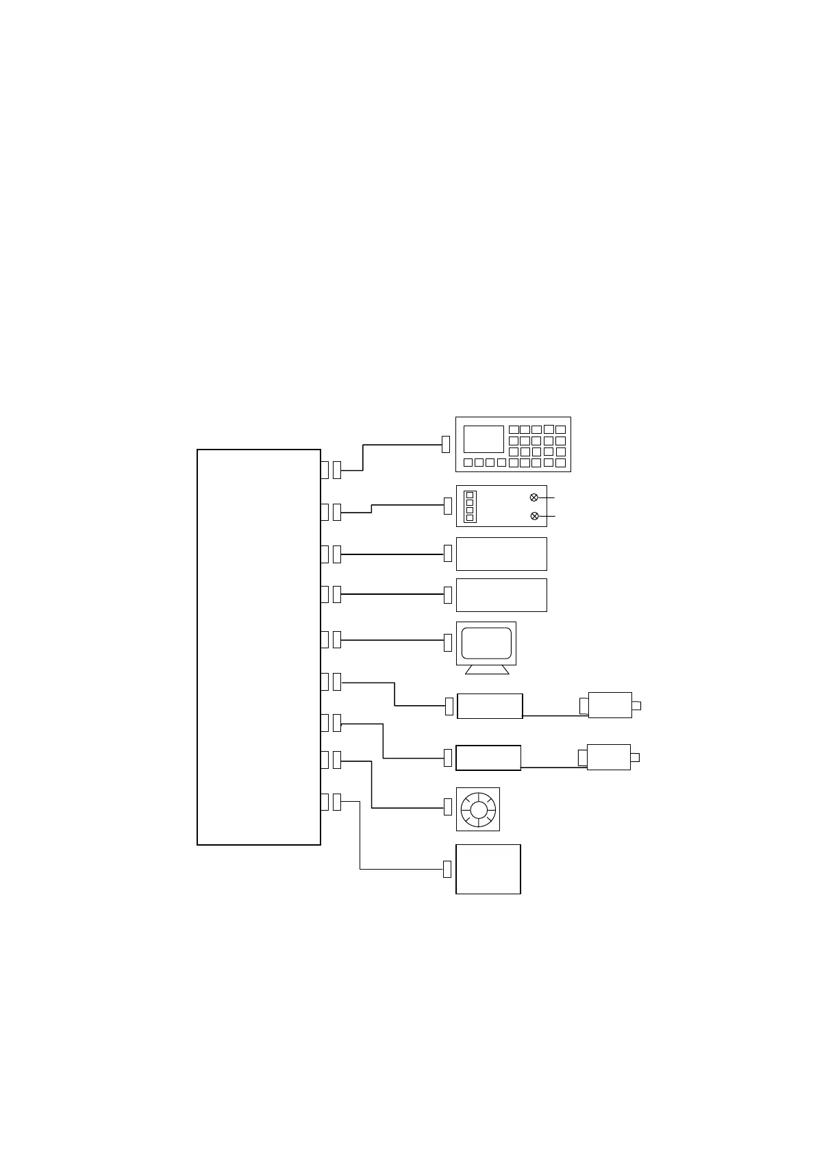
The HUST H2N system generally has the following configuration as shown in Fig. 2-1.
The main components of this configuration are listed below.
1. CPU Main Board
2. Keyboard Unit
3. MPG Hand-wheel
4. RS232 Communication Interface
5. Servo Driver and Motor
6. Power Supply
7. I/O Relay Board
8. Analog Output for Spindle Drive (0~10V)
Fig 2-1 System Configuration
Keyboard (2)
Servo Motor (5)
Driver
MPG(3)
RS232C (4)
Servo Motor (5)
Driver
X-Axis
Y-Axis
CPU
Main
Board
(1)
OUTPUT
Standard O (7)
INPUT
Standard I (7)
R
Power Supply (6)
(AC 220V)
JP2
JP1
P1
P2
P7
P4
P5
P3
P6
D/A (8)