5 I/O Interface Connections
5 - 1
5 I/O INTERFACE CONNECTIONS
5.1 I/O Connector Pin Assignment
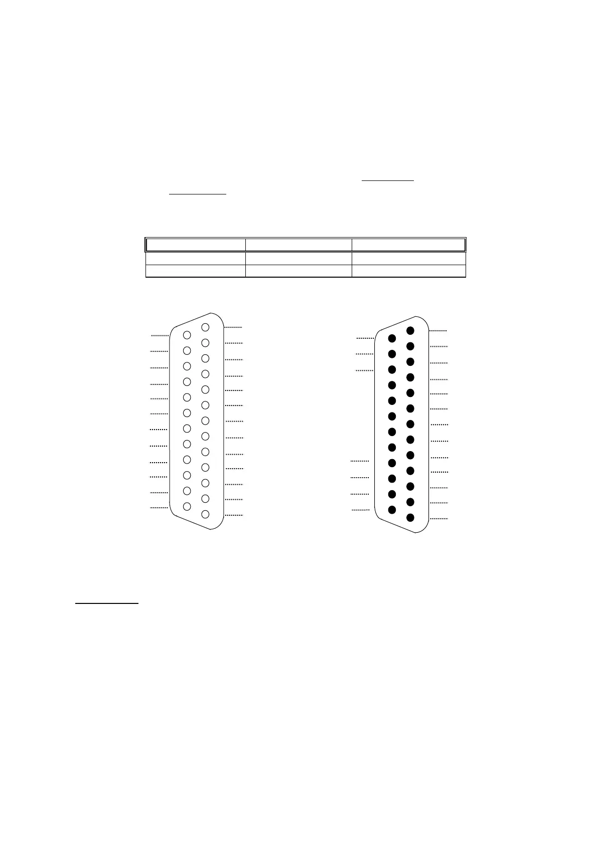
The pin assignment of 25-pin connector is shown in Fig 5-1. This assignment is
standard in HUST controller and can be applied to those connectors on main board,
input board, or output relay board. The connector designation on H2N controller is
shown in Table 5-1. Note that the input connector has 24 I-points while output
connector has 16 O-points.
Table 5-1 I/O Connector Designation and Pin Assignment
Connector Designation Connector Type I/O Pin Assignment
P1 DB25LM (Male) O 000 ~ O 015
P2 DB25LF (Female) I 000 ~ I 023
Fig 5-1 I/O Connector Pin Assignment (NPN-type)
I/O signals can be connected directly to P1 and P2 connectors on H2N controller. All
output points on HUST H2N main board are of transistor type circuit with open collector.
However, it would be advisable to use input board and output relay board before the
signal going into the controller. This provides additional protection for main board on
CNC from being damaged by electrical surge.
25
24
23
22
21
20
19
18
17
16
15
14
13
12
11
10
8
7
6
5
4
3
2
1
12
11
10
09
08
07
06
05
04
03
02
01
00
P2, Input Pin Assignment (Female)
GND (24V)
23
22
21
20
19
18
17
16
15
14
13
GND (24V)
GND (24V)
+24V
+24V
00
01
02
03
04
05
06
07
08
09
10
11
12
13
14
15
P1, Output Pin Assignment (Male)
25
24
23
22
21
20
19
18
17
16
15
14
13
12
11
10
8
7
6
5
4
3
2
1