HUST H2N Connecting Manual
5 - 2
5.2 Input Board and Output Relay Board
The input signal connection can be done in two ways:
1. Connect directly to DB25LF connector in the controller shown in Fig 5-1.
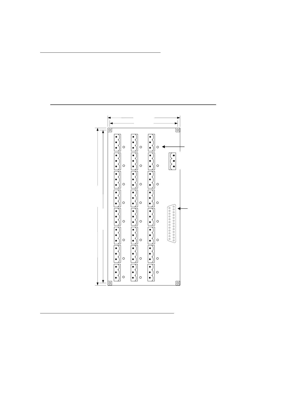
2. Connect input signal to the corresponding terminal of HUST input board, then
connect from DB25LF connector on the board to the connector on the controller
box. HUST input board is shown in Fig 5-2. The advantage of using input board
is to protect the controller circuits from being damaged in case of short circuit.
This method of connection is suitable for NPN-type input connector only.
Fig 5-2 HUST Input Board (NPN-type)
The output signal connection can also be done in two ways:
1. Connect directly to DB25LM connector in the controller shown in Fig 5-1.
2. Connect output signal line from external device to the corresponding terminal of
output relay board, then connect from DB25LM connector on the board to the
connector on the controller box. HUST output board is shown in Fig 5-3. The
LED
+24V
GND
I07
I06
I05
I04
I03
I02
I01
I00
I15
I14
I13
I12
I11
I10
I09
I08
I23
I22
I21
I20
I19
I18
I17
I16
72
64
155
147
DB25LF
24V Power Input
GND
24V