HUST H2N Connecting Manual
5 - 4
The input signal I007 is specially reserved for G31 skip function. All other 23 input
signals and 16 outputs are free for customer’s use.
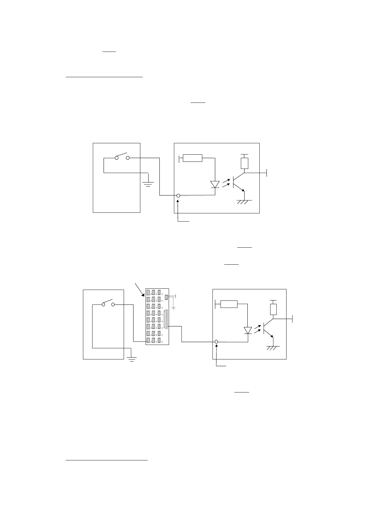
• Input Signal Specification : The voltage to drive the input signal is 24V, but the
signal line is connected to the “sink” end (0V). The current is 8 mA.
• Input Signal Directly Connected to CNC (NPN-type)
Input signal bypasses the input board and is directly connected to P2 connector
on CNC.
Fig 5-4 Input Signal Directly Connected to CNC (NPN-type)
• Input Signal Connected to Input Board then to CNC (NPN-type)
Fig 5-5 Input Signal Connected to Input Board (NPN-type)
5.4 Output Signals
Output signal is the one from CNC controller to an external device. The output
circuit of HUST H2N controller is a transistor circuit that can be used to drive a relay
or LED, etc.
• Output Signal Specification:
Si
nal Contac
R
External Tool
24V
DB25LF Input
R - 3.3K
CNC
5V GND
5V
0V
External
Signal Contact
Input Board
0
24V
R
DB25LF Input
R - 3.3K
CNC 5V GND
5
24V
I-00