HUST H2N Connection Manual
6 - 36
When you start execution, the tool starts moving while the controller begins
pre-fetching process. At block N003, the controller stops pre-fetching process
(G31) and the controller will wait until N003 block is executed. Assume G31
causes the tool to jump off at X=425. At block N004, the controller execute
“V#1 = V#12021” (current tool position on X-axis) and V#1=425000.
6.5 Input and Output Signal (I-Bits & O-Bits)
1. HUST H2N controller provides 24 I-bits (I00~I23) and 16 O-bits (O00~O15).
Among them, I00~I03 are of high speed with a response time of 50 μsec.
2. All input and output signals are defined as ON = 1 (high) and OFF = 0 (low).
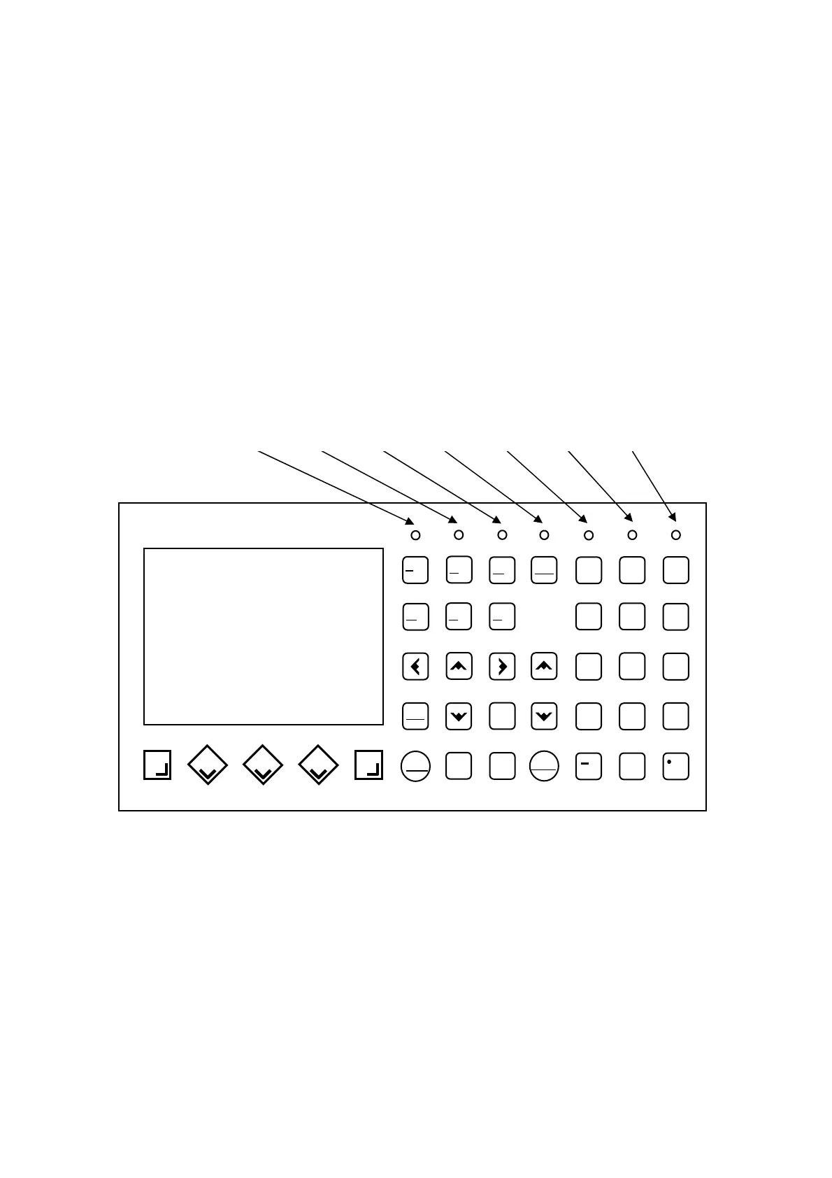
3. HUST H2N keyboard provides 7 LED for user’s application. They are output
bits and are designated as O192 ~ O198 as shown in the figure below. User can
incorporate these bits into PLC for display. They are ready and no external
connections are necessary.
INPUT
L
F
CURSOR
NEW
LINE
DEL.
R
S
I
M
P
G
U
X
RESET
SHIFT
7
1
4
JOG
HOME
8
0
2
5
TEAC
EDIT
9
6
3
TAPE
PRNO
HUS
CNC - 2
CYCST
PAGE
MDI
AUTO
O198 O197 O196 O195 O194 O193 O192