6 Interface Between CNC And PLC
6 - 3
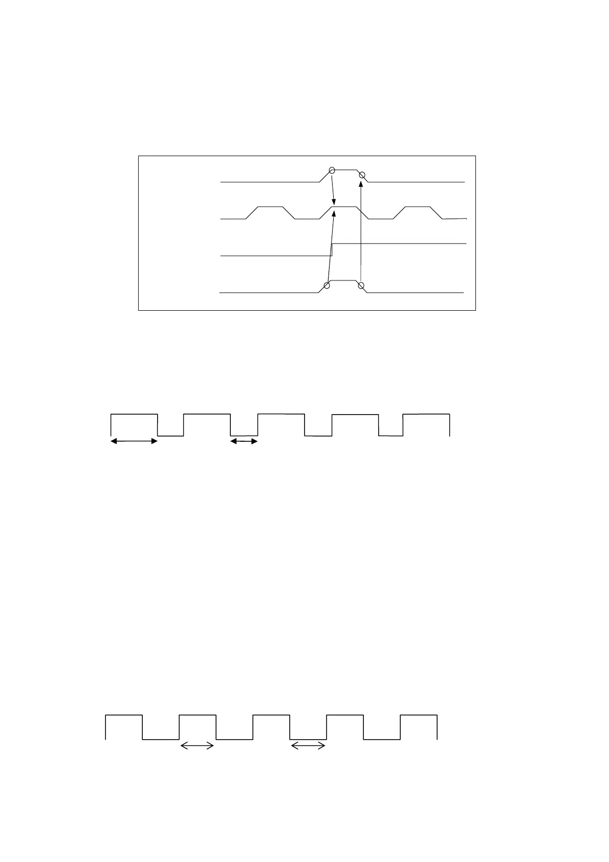
6.1.1 S-bit Signal and PLC Cycle Time Chart
Fig 6-1 shows the time chart between the HUST H2N controller and the PLC unit.
Note that Bit S017 is synchronized with Bits S000 ~ S023. S000 ~ S031 are all one-
shot signals.
Fig 6-1 Time Chart Between HUST CNC and PLC
6.1.2 Descriptions of S-bits
• Square Wave Signal with 0.75 sec ON, 0.25 sec OFF (S000)
• Reset Key Strobe (S001)
The controller sends S001 one-shot high (1) strobe to PLC unit when RESET key is
pressed.
• Cycle Start Key Strobe (S002)
The controller sends S002 one-shot high (1) strobe to PLC unit when CYCST key is
pressed.
• Square Wave Signal with Wave Period (S008~S011)
S008, signal ON = 0.10 sec and OFF = 0.10 sec.
S009, signal ON = 0.25 sec and OFF = 0.25 sec.
S010, signal ON = 0.50 sec and OFF = 0.50 sec.
S011, signal ON = 1.00 sec and OFF = 1.00 sec.
One Shot S-Bit
S000~S031
Continuous
S032~S096
1
2
3
PLC Cycle
Key Strobe S017
0.75 sec
0.25sec
ON Time
OFF Time