6 Interface Between CNC And PLC
6 - 17
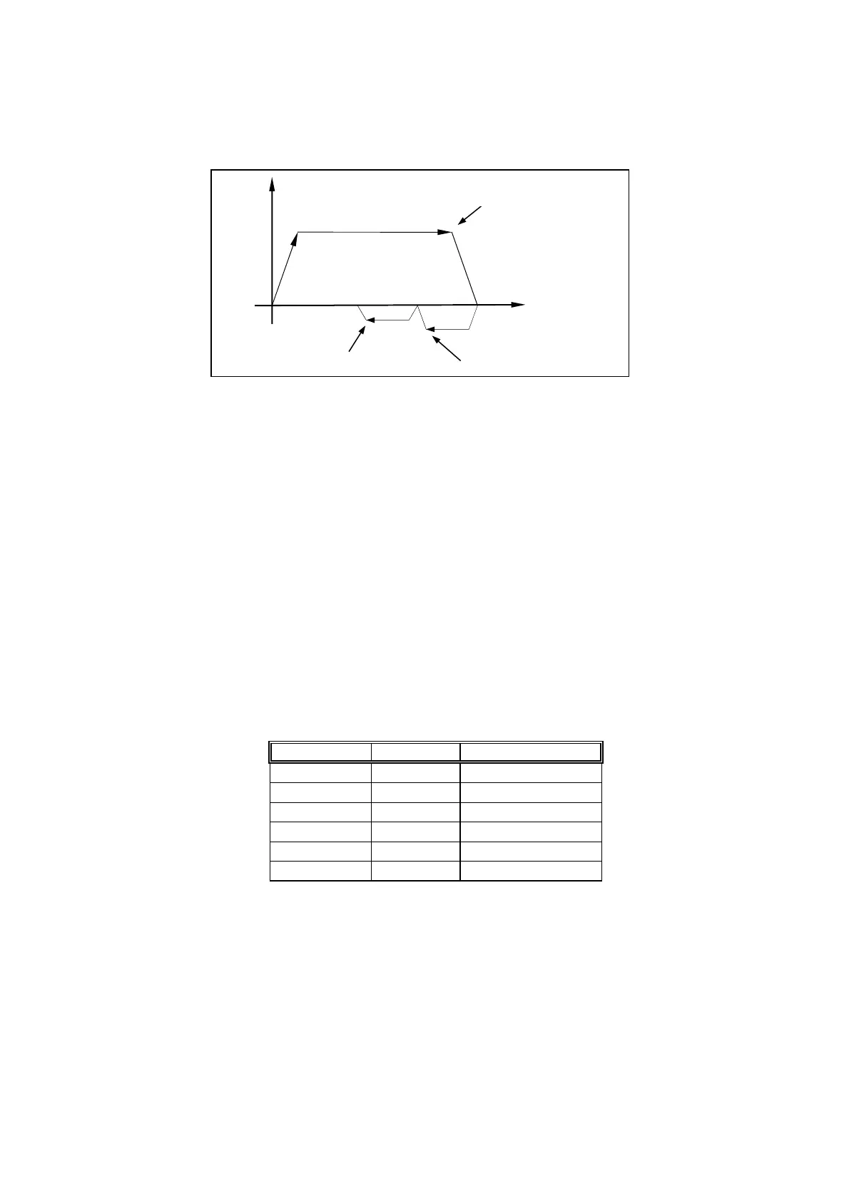
To find HOME position for Y-axis, the same procedures described above apply. Fig
6-7 is a typical time chart for HOME execution.
Fig 6-7 Time Chart for HOME Execution
• Specify Work Coordinate Group as Working Coordinate (C123)
Set the Current Program Position as Working Coordinate (C080~C081)
C123 = 1~0 (falling edge), use the data in MCM parameters as the current work
coordinate.
C080 = 1~0 (falling edge), use the current program position for X-axis as the work
coordinate origin.
C081 = 1~0 (falling edge), use the current program position for Y-axis as the work
coordinate origin.
HUST H2N controller provides 6 groups of work coordinate (G54~G59) with their
location (with respect to HOME) data stored in MCM #1~#12 as shown in Table
below. Also shown is the group designation that is stored in register R228. (See
Table 6-4 for Registers) The default setting of work coordinate system is G54. To
change work coordinate, please follow one of the methods described below.
Work Coord. MCM No. Group No. by R228
G54
1
∼
2
0
G55
3
∼
4
1
G56
5
∼
6
2
G57
7
∼
8
3
G58
9
∼
10
4
G59
11
∼
12
5
Table 6-3 Work Coordinate
1. When in MDI or AUTO mode, execute one of G54~G59 function in the
program. Press “RESET” will restore the work coordinate back to default G54
system. For example, the program below is in G54 system when power-on. It
starts executing under AUTO mode and it changes to G55 system at block N10.
Once it finishes execution, press RESET will restore to G54 work coordinate
system.
Step1
Step3 Step2
Tool position
Tool
Speed
Leaving Home Limit Switch Found Encoder Index
Touching Home Limit Switch