5 I/O Interface Connections
5 - 5
a) With I/O relay board, each connection point on the board can withstand a
maximum of AC 250V and 10A current.
b) Without I/O relay board, the output transistor circuit of HUST H2N
controller is rated at a maximum of 35V and 500 mA of current.
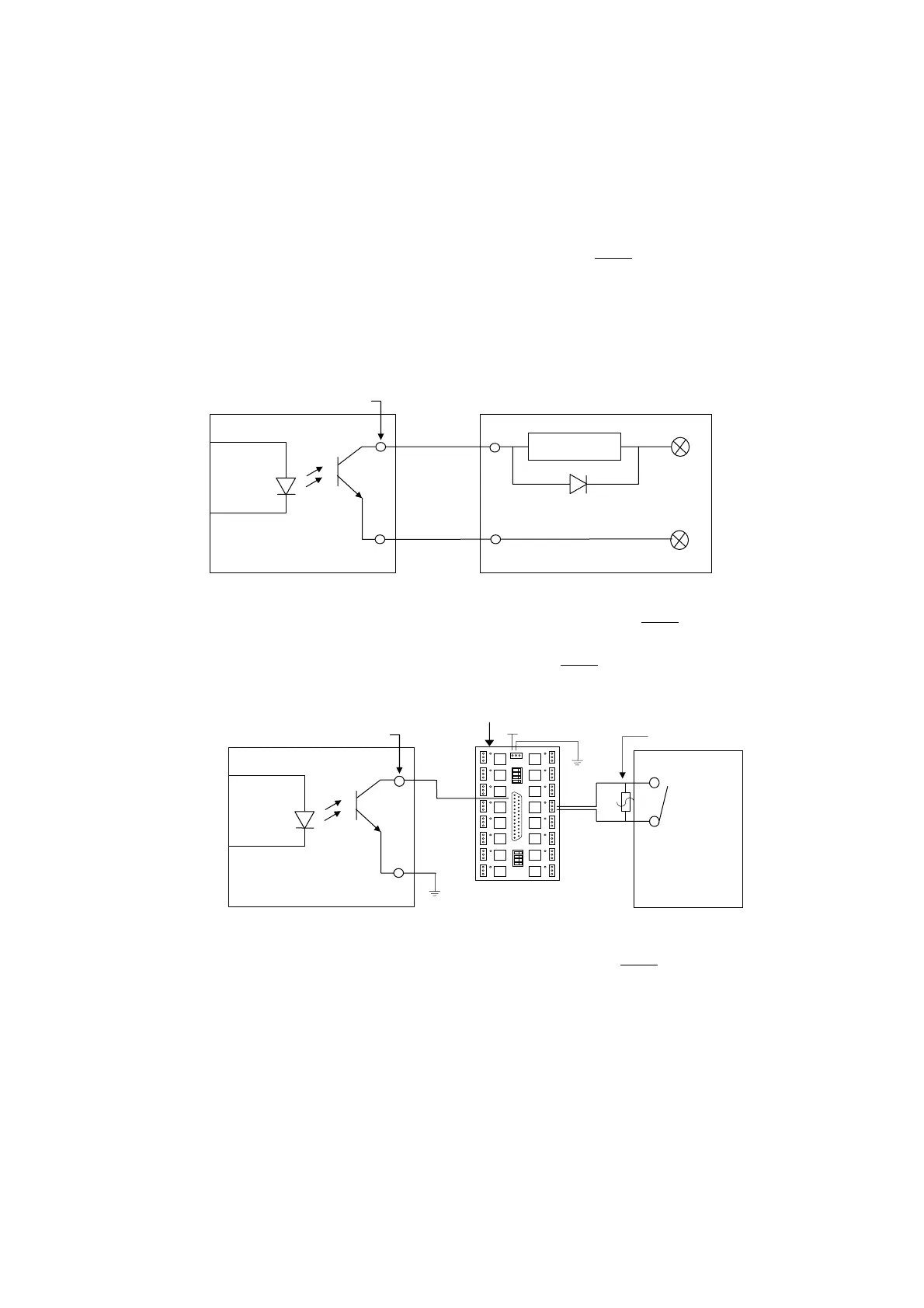
• Output Signal Directly Connected from CNC to Tool (NPN-type)
When output connector is directly connected to an inductive load, such as relay,
it must connect a spark killer diode in parallel and as close to the load as
possible. (See Fig 5-6) ll output terminal of HUST H2N controller is open
collector transistor circuit.
Fig 5-6 Output Signal from CNC without Relay Board (NPN-type)
• Output Signal Connected to Output Relay Board (NPN-type)
Fig 5-7 Output Signal Connected to Relay Board (NPN-type)
5.5 Emergency-Stop Circuit
The electronic circuit in the controller requires about 100 milli-seconds to reach
stable state when power is turned on. During this unstable period, the servo motor
should not be turned on. To accomplish this purpose, HUST internal PLC has a
"Servo-on Timer" with 1.5 seconds. When the timer is up, the controller sends an O-
bit high (1) to turn on the servo driver.
RELAY
Ext. Device
Spark Killer
CNC Side
DB25LM Pin
DB25LM Output
Output Board
Spark Killer
CNC Side
0V
24V
0
O
Ext. Tool