HUST H2N Connecting Manual
5 - 6
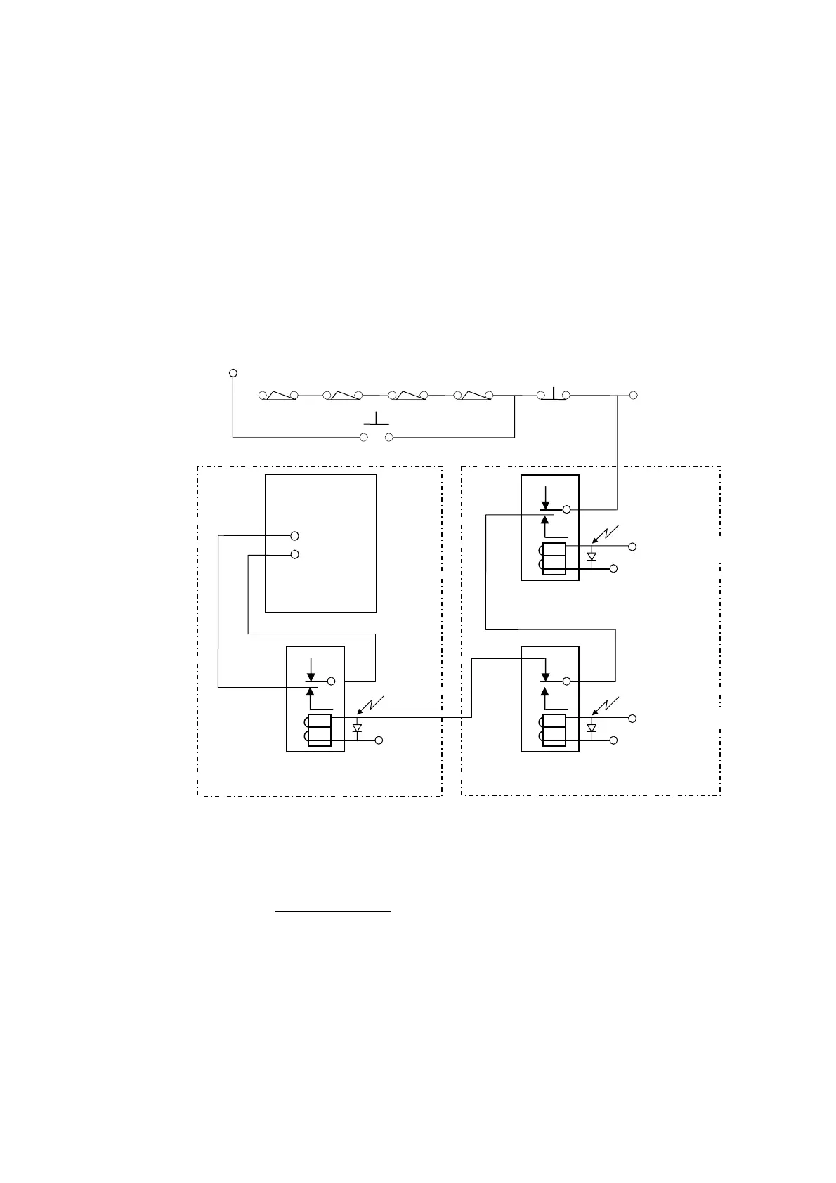
Fig 5-8 is an emergency stop circuit. When the hardware OT limit switch is touched
or the E-stop button pushed, the controller will be in a state of emergency stop and
the servo-on switch on the servo motor will trip off. For safety reason, the E-stop
button, the hardware OT limit switch, and the E-stop relay should be connected in-
series and the servo-release button in-parallel with the hardware OT limit switch.
Please note that the E-stop button and the hardware OT limit switch are of normal-
closed type.
During normal operating condition, the servo-release button is at OFF position. After
emergency stop has occurred and all power to servo motor has been cut off, servo-
release button can be pushed in to supply power to servo motor to bring the machine
tool to normal operating range.
Fig 5-8 Emergency Stop Circuit
Notes on Emergency Stop Circuit (Fig 5-8):
1. Relays A and B are protection circuit during power-on. The purpose is to prevent
the tool from being damaged in case of power-on failure that results in a total
output.
2. Relay C is a servo-on relay.
3. Generally, Relay C has multiple connecting points for multiple servo. Each servo
motor requires independent connecting point. Do NOT connect servo motors in
parallel because some servo motors cannot be connected in parallel. See Fig 5-7
and Fig 5-8.
Spark Killer
External Relay B
24V
Spark Killer
External Relay A
24V
Servo Driver
Servo-On
Signal
Spark Killer
SERVO ON Relay C
24V
+24V GND
Limit Switch
(E-Stop)
INPUT
Servo Release
PLC Output
PLC Output