5 I/O Interface Connections
5 - 7
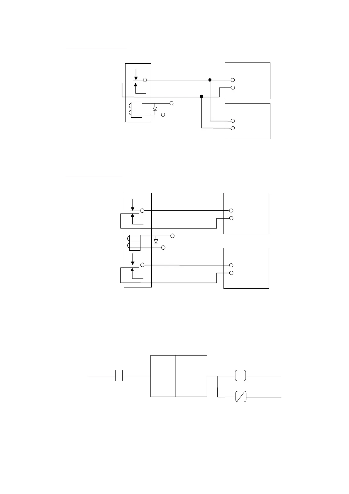
Incorrect Connection:
Fig 5-7 Incorrect Connection
Correct Connection:
Fig 5-8 Correct Connection
4. Relays A and B are connected to two (2) outputs from PLC. Example of servo-on
in PLC is shown in Fig 5-9 below.
Fig 5-9 Servo-on arrangement in PLC Program
PLC Output
Relay C
24V
Servo Driver
Servo-On
Signal
Servo Driver
Servo-On
Signal
24V
PLC Output
Relay C
Servo Driver
Servo-On
Signal
Servo Driver
Servo-On
Signal
A 0127
O 0000
O 0000
TMR
50
msec
T 000
#30