Pg 3.3 V18 2001e
STEP SIX Remove the blade from the carbide guides by pulling out.
STEP SEVEN Remove the blade off of the wheels. Gloves are a necessity.
STEP EIGHT Place the new blade onto the wheels in correct orientation, teeth pointing down as they
pass through the guides and facing the operator.
STEP NINE Turn hydraulics ON. Tension
partially.
Turn hydraulics OFF.
STEP TEN Place the new blade into the carbide guides (by twisting the blade) until seated.
STEP ELEVEN Turn hydraulics ON. Set Blade Tension switch to "+/RUN".
STEP TWELVE Start the blade for a few rotations. This allows the blade to fully seat in the carbide
guides and track onto the wheels.
FINAL STEP Close the carbide guide locks, close the blade guard and close the Idler and Drive
doors. Break-in blade.
BLADE TRACKING
First, inspect the blade wheels for wear or damage and repair as required. Blade tracking adjustment should
always begin at the wheel where the tracking is farthest out of specification. Using the instructions below, adjust the
worst wheel, jog the blade and check both wheels. Repeat this process until both wheels are within specification
(.200-220" of tooth over hang from the front of the wheel). Both the drive and idler wheels are factory set a certain
distance from the wall behind the wheel. Adjustment should not be required unless the wheel is being replaced. On
the drive wheel there is a large hex head bolt and four set screws in a "push/pull" arrangement. For the idler wheel
there is single adjuster assembly in the centre of the idler shaft under the cover on the front of the head. Hyd-Mech
Service should be contacted before making any adjustment to the wheel position.
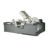
DRIVE WHEEL ADJUSTMENT
Adjustments should be made with the blade tension
released slightly. The drive wheel has two mounting bolts and
two adjusting bolt assemblies. The mounting bolts (A) should
be loosened but remain snug before making any adjustment to
the bolt assemblies (B & C). Both of the bolt assemblies
should be adjusted by equal amounts. To adjust the bolt
assemblies, release blade tension slightly, loosen bolts "B"
and turn bolts "C" in or out by equal amounts and tighten bolts
"B". Turning bolts "C" in will pull the blade onto the wheel and
turning them out will push the blade off the wheel. Check the
tracking movement after each one quarter turn of bolts "C" by
running the blade at minimum speed. When the tracking is
within specification, tighten bolts "A".
TURN THE HYDRAULICS OFF !
C
B
Drive wheel mounting bolts and tracking bolt
assemblies.
A