Pg 3.4 V18 2001e
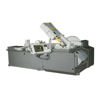
Blade brush & adjusting
screw (circled).
B & C
A
B
A
A
C
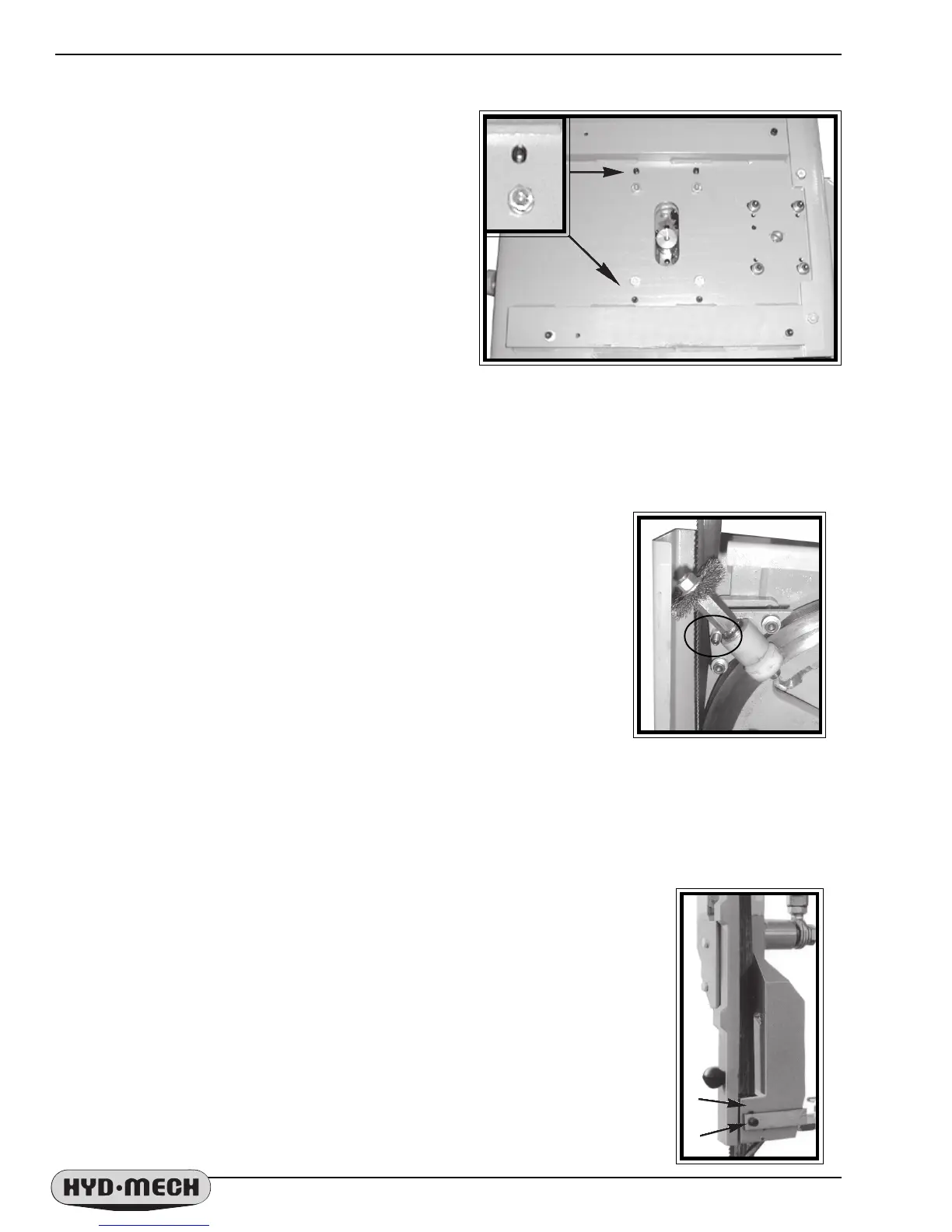
Idler wheel tracking bolts (A) and set
screws (B & C) with the cover removed.
IDLER WHEEL ADJUSTMENT
Adjustments should be made with the blade tension
released slightly. Remove the cover on the left side of the
head. There are four hex bolts (A) and four set screws (B &
C). Bolts A are loosened and then set screws B & C" are
adjusted by turning one out, the other in 1/4 turn and
tightening the first again. Adjust by 1/4 turn at a time and
check the blade movement with each adjustment by
running the blade at minimum speed. Loosening B and
tightening C will push the blade off the wheel. Loosening C
and tightening B will pull the blade onto the wheel.
BLADE BRUSH ADJUSTMENT
The blade brush is properly set when the machine leaves the factory but it will
wear during operation and needs to be adjusted periodically. The blade brush
assembly is shown below. In order to adjust it, the nut on the adjusting screw
needs to be loosened and the screw turned counter clockwise to move the brush
closer to the blade until the wires on the brush touch the bottom of the blade
gullets. If a new brush is being installed, then the adjusting screw must be turned
clockwise in order to move the new brush away from the blade so that the wires
are touching the bottom of the gullets.
If the brush gets worn to approximately 70% of its original 3" diameter it should
be replaced. A brush may be purchased from your HYD-MECH dealer.
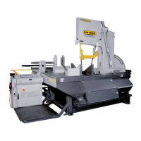
BLADE GUIDES
Both guide arms are provided with blade guide assemblies consisting of carbide
pads that are integral to the correct guidance of the saw blade. These guide assemblies
will require an adjustment periodically, refer to Troubleshooting in this section for
indications that adjustment is needed. To adjust the pads properly, follow this simple
procedure. With the lever in the locked position, loosen the small set screw (A) in the
edge of the lever. Turn the adjusting set screw (B) clockwise until tight and then loosen
it 1/8th of a turn. With the lever still in the locked position, tighten the small set screw
in the side of the lever. This should put just enough pressure on the blade to permit you
to push the blade out approximately 1/8".
In the event that the pads must be replaced, refer to the
exploded parts drawing in Section 6.
Blade guide
adjusting screws.
A
B