B
Bethany HarrisAug 3, 2025
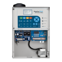
Why does my HydroPoint Controller show high current between 20% to 50%?
- BBrad FigueroaAug 3, 2025
A high current reading (20% to 50%) on your HydroPoint Controller suggests a potential issue on the 2-wire system, leading to increased power consumption. This problem may worsen in wetter conditions.