宏宇达数控 & 弘宇达智能
地址:深圳市南山区中山园路 1001 号 E4-6C(TCL 国际 E 城)
TEL:0755-26625800 FAX:0755-26729960 -25-
5.Test Introduction
5.1 Manual reference point (16 points) calibration
1. Set the measurement range limit (maximum 25mm)
2. In the main menu, press <F1> to enter the [Calibration] menu, and then enter the "16-
point calibration" menu.
3. Start calibration, move the cutting head to the first point, press [Enter] to confirm
4. Move in order and confirm the remaining 15 points
5, confirm or cancel the exit, the end of the calibration
5.2 Automatic reference point (16 points) calibration
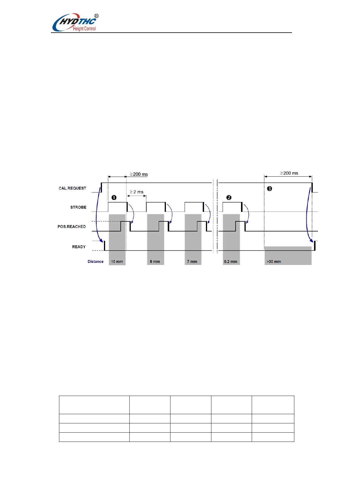
The automatic calibration control timing diagram is as follows:
1. Change or confirm the measurement range limit (maximum 25mm).
2. Set the CAL.REQUEST signal (PIN A3, High).
3. Move the sensor to the workpiece until the COLLISION signal is set (PIN A11 is high),
that is, touch the workpiece and find the zero point required for calibration.
4. Move to the first reference point (measurement range limit value).
5. Set the STROBE signal (PIN A7, High) to confirm that the reference point has been
reached.
6. STROBE must be maintained for more than 200ms before the POS.REACHED signal
is read. The POS.REACHED (PIN A15, High) signal confirms that the measured value
has been accepted by the CNC/PLC.
7. Process the remaining 15 reference points separately.
For example: