Page 53
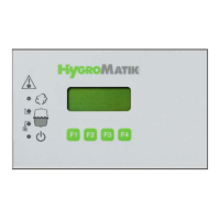
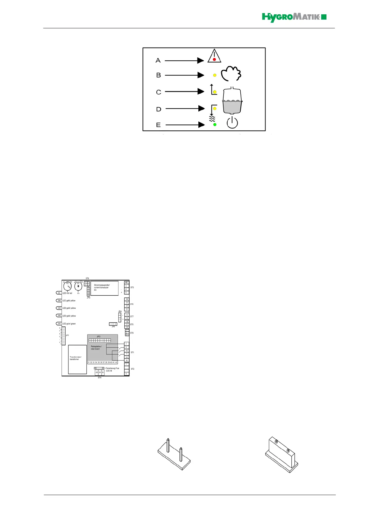
A: Malfunction (red LED)
B: humidifying (yellow LED)
C: Filling (yellow LED)
D: Blow-down (yellow LED)
E: Stand-by (green LED)
LED B, C, D and E represent the following operational conditions:
LED B: Steam production (main contactor is switched)
LED C: filling water
LED D: draining water
LED E: power supply for control is on
The red LED A blinks to indicate a humidifier malfunction. The humidi-
fier shuts off automatically, see Section „Malfunctions and Messages /
Conditions“.
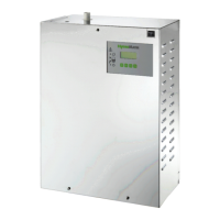
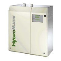
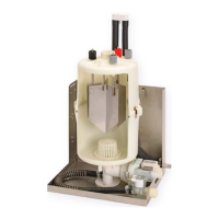
7.2 Basic-DS Main PCB
Also see the detailed illustration of the main PCB in chapter: „Basic
PCB Connections“
On the main PCB, jumper strip JP1 and two potentiometers are
located; control function is determined by how these are set. Descrip-
tions of this appear in the following sections:
7.3 Parameter Setting with Jumpers
Normally, settings (parameters) for the Basic-DS Control can only be
modified using jumpers.
Jumpers are small blocks with two pins over which a circuit plug can be
placed, creating an electrical contact inside the plug.
Example: jumper open jumper jumpered