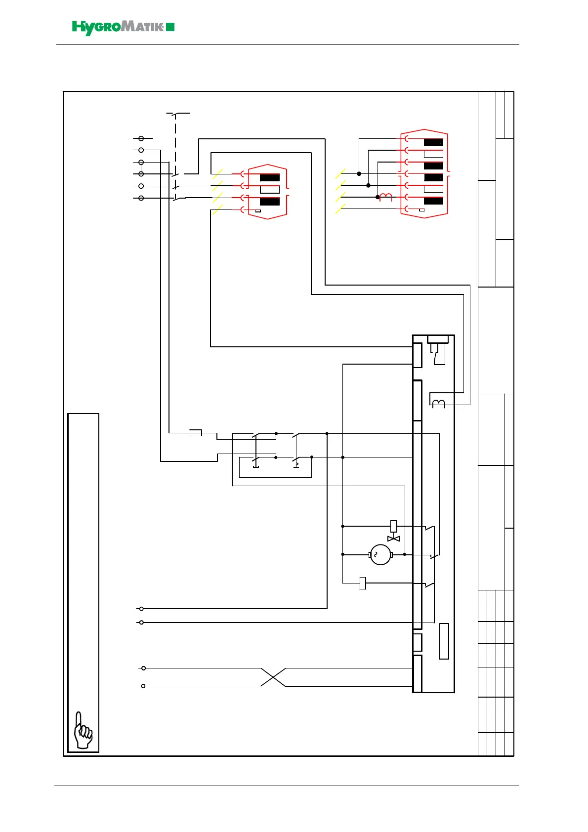
15. Wiring Diagram
Änderung Datum Name
Bearb.
Gepr.
Norm
Datum
Urspr. Ers.dErs.fZust.
Blatt 1
von 1 Bl.
(Zeichnung Nr.)(Benennung)
(Datei)
Hy05-45,C06-58 BDS,CDS,CPDS
S-043100
S-043100D.001
HYGROMATIK
Lise-Meitner-Str. 3
D-24558 Henstedt-Ulzburg
Germany
Telefax
+49-(0)4193 / 895 - 33
Phone
+49-(0)4193 / 895 - 0
Lue 16.08.04
Lue
6
7
X1
2 1
Y1
M
M1
S1b
S1a
K1
HY05-17
C06-17
B1 L1 L2 L3
1,6A
F1
c
14.07.05
BDS
d
04.10.05
S1a+b
K1
1
2
3
4
5
6
X1
L1 L2 L3 L3 N PE
7
8
Standard 400/3/N/50-60Hz
input temerature sensor
Eingang Temperaturfühler
Meldung
Befeuchten
signal
humidifing
ST7
ST5
17
18
7
6
29 3028
ST2
15
42
4
3
5
2
9
10 11
16
13 12
Basis Platine/ basic electronic
ST1
ST3
B3
Sockel / socket
ST4
B3
Stromwandler
current transducer
B1 L3 L2 L1 L3 L2 L1
Hy23-45
C-30-58
Interlock system or On-Off-Remote Control or Bridge
Sicherheitskette
oder An-Aus-Fernschalter oder Brücke
e Beschrift. 1+2 03.11.09 Kb
br sw
Note: The steam generator is only operationable if the contact
across terminal 1 and 2 (the safety interlock) is closed.