Maintenance and RepaiR
powermax
45
Operator Manual 5-7
Replacement
1. Hold the Mylar barrier so that the edge with the
3notches is on the left and the edge with 4notches is
on the right.
2. There is a perforation across the top, about 4.45cm
(1.75 inches) down from the top edge. If you are
replacing the Mylar barrier with a new one, you will need
to fold it along this perforation so that the top edge
bends away from you.
3. Position the barrier so that the folded section will cover
the top of the power board. Slide the barrier into place
with the bottom edge between the ribs on the base
and the power board. The notches on each side of the
barrier should align with the ribs on the inside of the end
caps.
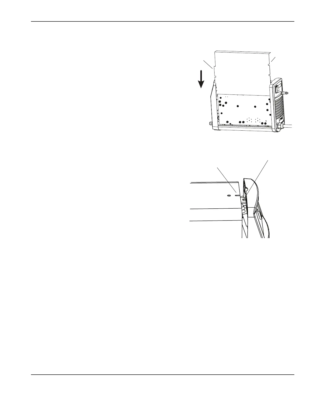
4. Being careful not to pinch any of the wires, slide the
cover back onto the power supply. Make sure that the
bottom edges are in the tracks and that the slot in the
top of the cover is aligned with the tab on the front end
cap so that the louvers in the cover are in front of the
fan. Position the handle over the holes in the top of the
cover, then secure the cover with the 2screws.
Three
notches
Cover slot
Tab
Four
notches
Replace the work lead (CSA and CE)
1. Turn OFF the power, disconnect the power cord, and disconnect the gas supply.
2. Use a #2Phillips screwdriver to remove the 2screws from the handle on the top of the power supply. Tip the end
panels back slightly so that you can get the edges of the handle out from underneath them. Lift the cover off the
power supply. Remove the Mylar barrier that protects the power board.
3. Remove the screw from J21 (also labeled “work lead”) on the power board that attaches the lead to the board. Set
the screw aside.
4. Gently tilt the front panel away from the power supply. From the inside of the panel, unscrew the nut that secures
the strain relief to the end cap.