9 © 2012 Installation and Reference Manual D0125 Rev. H
Section 2 — Installation Preparation Checklist
1. Read all instructions, especially the Important
Information in Section 1 at the beginning of this
manual, before you install the operator. This
section is focused on mechanical installation.
For electrical setup and use of the Smart Touch
Controller, refer to Section 3.
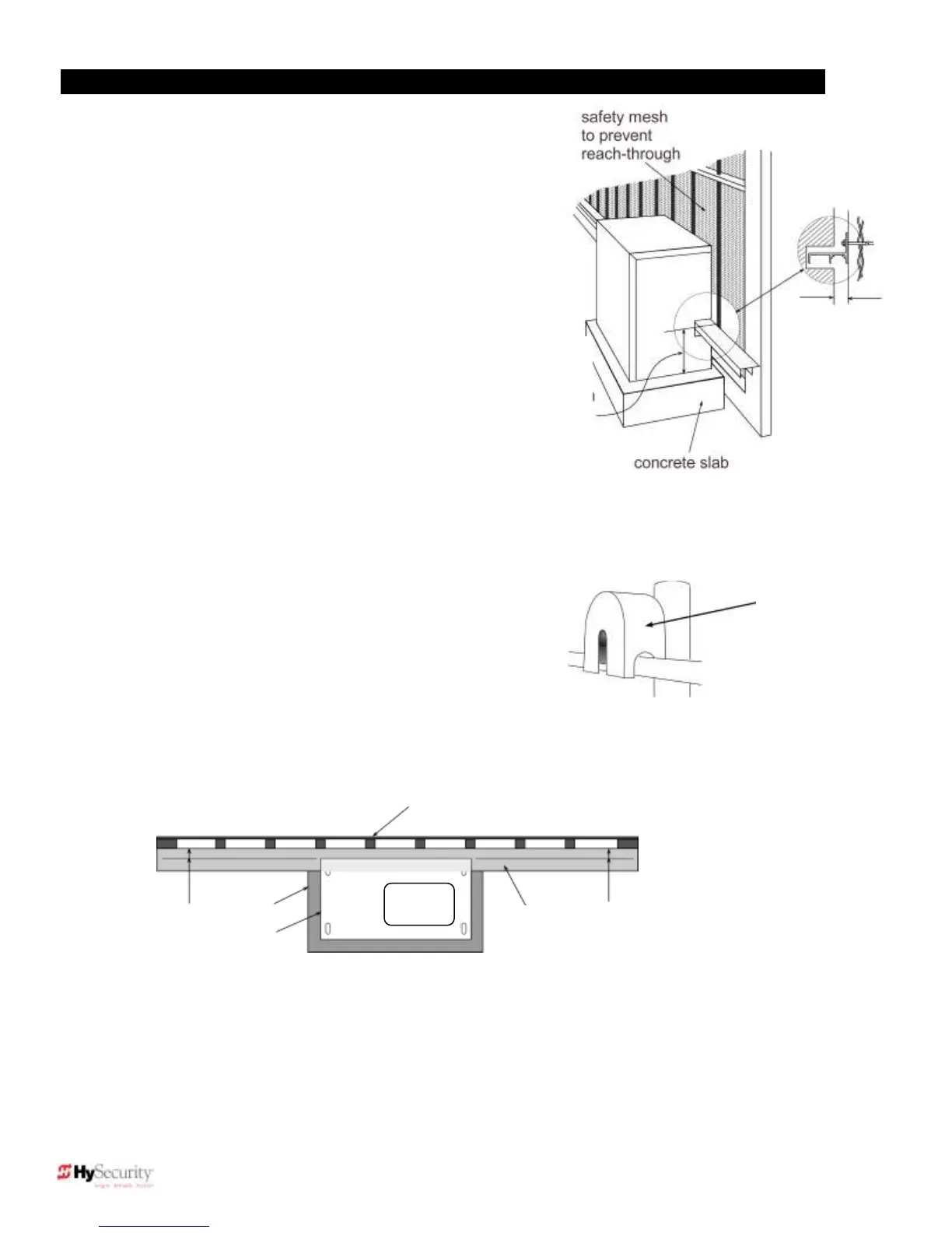
2. Make sure the concrete pad is the
recommended size and ready for operator
attachment. Also, check that electrical conduits
are correctly located and in proper alignment
with the chassis. HySecurity recommends that
the concrete pad reaches below the local frost
line and extends somewhat above grade. See
the footprint plan and elevation view on pages
14 and 15.
3. Make sure the gate rolls smoothly in both directions
without any gate hardware binding. If the gate is warped
or hard to move, stop and fix the gate before attempting
to automate it.
4. Verify that you have covers for all exposed gate support wheels.
These must be installed. Also, look around to identify all potential
pinch points and hazardous areas and plan the best location for
entrapment protection devices and warning signs. Remember you
are required to advise the owner regarding potential hazards and
to discuss the use of the entrapment protection sensors that you
have selected and installed.
5. There are three steps to a perfect install: location, location, location.
One of the most critical installation aspects is to make sure the operator is positioned the proper distance
from the gate and the gate and operator are as parallel as possible. See Figure C below. Prepare shims to
align the drive rail.
NOTE: If necessary, shim the drive rail so that it is straight ( ¼ inch) throughout the
gated travel distance.
Remember to
cover all four of
the cantilever
gate wheels
Gate distance
from operator:
Drive rail
location
9 ¼″from top
of slab to top
of drive rail
1¾″between
fence and
operator.