32 © 2012 Installation and Reference Manual D0125 Rev. H
Section 4 —Entrapment Protection Devices for Sliding Gates
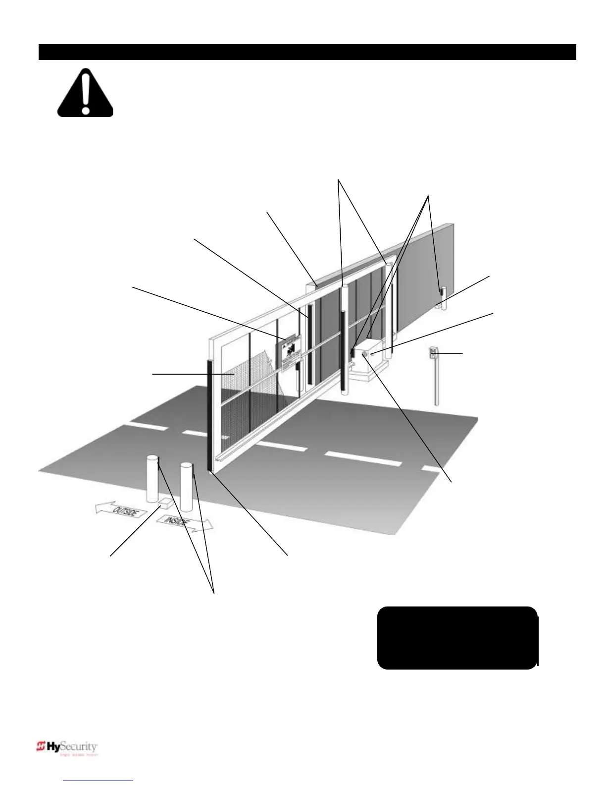
Entrapment Protection Device
Schematic for Sliding Gates
Keep this gap as
small as possible
Warning signs must be
on both sides
2 ¼” safety mesh
prevents reach-
through: height not
less than 48 inches
Physical travel
stop, both ends
Photo Eyes for
both directions
each side of gate
Gate edge sensor,
on leading edge
and trailing edge
Note: Wheels and covers are
not shown. However, all gate
wheels must be covered.
This schematic view is not meant to recommend a specific configuration. It is not meant to point out
the important elements of a proper automatic vehicular gate installation. The gate operator is only
one component in the total system. Always install a separate pedestrian gate.
Access controls
at least six feet
away from gate
and operator
Physical travel
stop, both ends
Photo Eyes for
both directions