12 © 2012 Installation and Reference Manual D0125 Rev. H
Section 2 — Installation
6. Electrical Power Connection
This operator is intended for permanent installation.
All electrical conduits must be properly connected to
the control box. The entry for the primary power is a
½ - ¾-inch knockout on the left side of the control box
next to the power switch. The operator is built to run
on a specific voltage and phase. Make sure you have
compared the available line voltage and phase with
the voltage and phase listed on the nameplate on the
machine. They must match! Be certain that the
branch circuit wire size versus the distance of the run
from the main panel is large enough to avoid excess
voltage drop. At a minimum, a 20A circuit (protected
with a 20A Inverse Time Breaker) should be provided.
Also be sure the operator is electrically grounded per
NEC Article 250 and local codes. See page 59 for
correct wire sizes and detailed electrical wiring
information.
7. Primary Tap of Control Transformer
Check to make sure that the primary tap on the control
transformer matches the line voltage you have
connected to the operator. Measure the line voltage
carefully to distinguish between 208V and 230V
branch circuits or between 390V and 460V branch
circuits. A label on top of the transformer identifies the
various voltage taps. This connection must match the
voltage on the operator nameplate.
8. Check the operator “Hand”
All slide operators must have their “handing” set
before they can function. The “handing” must be
set both by the proper hydraulic hose connection
and by programming the Smart Touch Controller.
The proper handing hose connection is described
on a label near the hose connection point. Also,
see the instructions to set handing on page 19.
Operators are shipped configured for right hand
operation. Handing is viewed by standing on the
secure side looking out. A gate which opens to the
right is a right-handed gate.
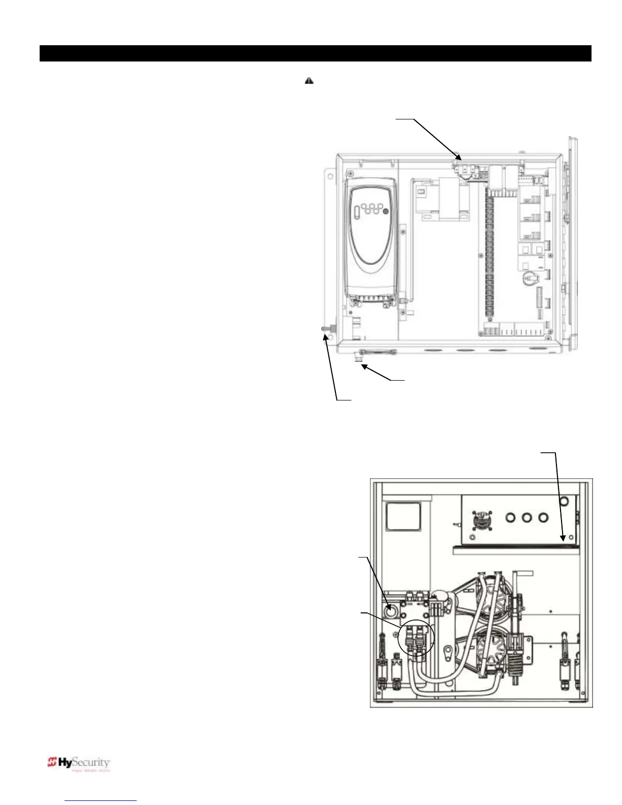
9. Replace the Shipping Plug!
Replace the ½″ steel or red plastic shipping plug
on the front side of the pump with the black
breather cap.
10. Setup the Smart Touch Controller
The operator controls will not allow the gate to function
until the Smart Touch Controller has been configured.
Wait to connect external controls until you have
reviewed Smart Touch Controller instructions and tested
operator basic functions.
CAUTION:
Variable frequency (VF) operators:
Make sure the connecting wires match the voltage
found on the operator’s nameplate. NEVER connect to
the white – 120V wire.
“Right Hand” shown
Remove red plastic
shipping plug and
replace with black
breather cap.
To change handing
connect hoses
according to label on
tank.