Game Control Adapter
The
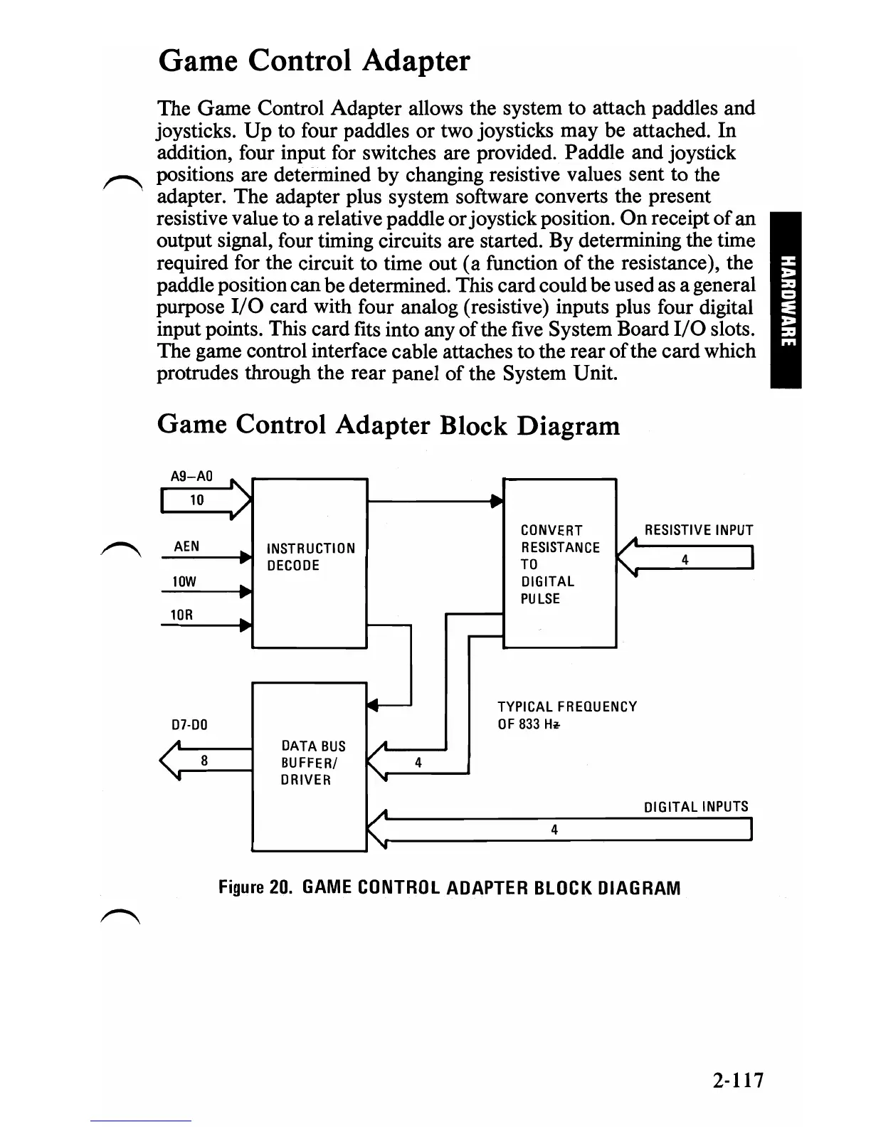
Game
Control Adapter allows the system
to
attach paddles and
joysticks.
Up
to four paddles
or
two joysticks
may
be attached. In
addition, four input for switches are provided. Paddle and joystick
positions are determined by changing resistive values sent to the
adapter. The adapter plus system software converts the present
resistive value to a relative paddle
or
joystick position.
On
receipt
of
an
output signal, four timing circuits are started. By determining the time
required for the circuit to time
out
(a
function
of
the resistance), the
paddle position can be determined. This card could be used as a general
purpose
I/O
card with four analog (resistive) inputs plus four digital
input points. This card fits into any
of
the five System Board
I/O
slots.
The game control interface cable attaches to the rear
of
the card which
protrudes through the rear panel
of
the System Unit.
Game Control Adapter Block Diagram
A9
-
AO
'\
..
I
10
...
/
..
CONVERT
A
RESISTIVE
INPUT
AEN
..
INSTRUCTION
RESISTANCE
...
4
DECODE
TO
K
I
lOW
..
DIGITAL
"
PU
LSE
lOR
-
..
.---
.....-
TYPICAL
FREQUENCY
07·00
OF
833
Ht
A A
DATA
BUS
,r
8
BUFFER/
4
...
DRIVER
"-
"
DIGITAL
INPUTS
A
4
I
....
"
Figure
20.
GAME
CONTROL
ADAPTER
BLOCK
DIAGRAM
2-117
 Loading...


