Programming the Mode Control and Status Register
The following
I/O
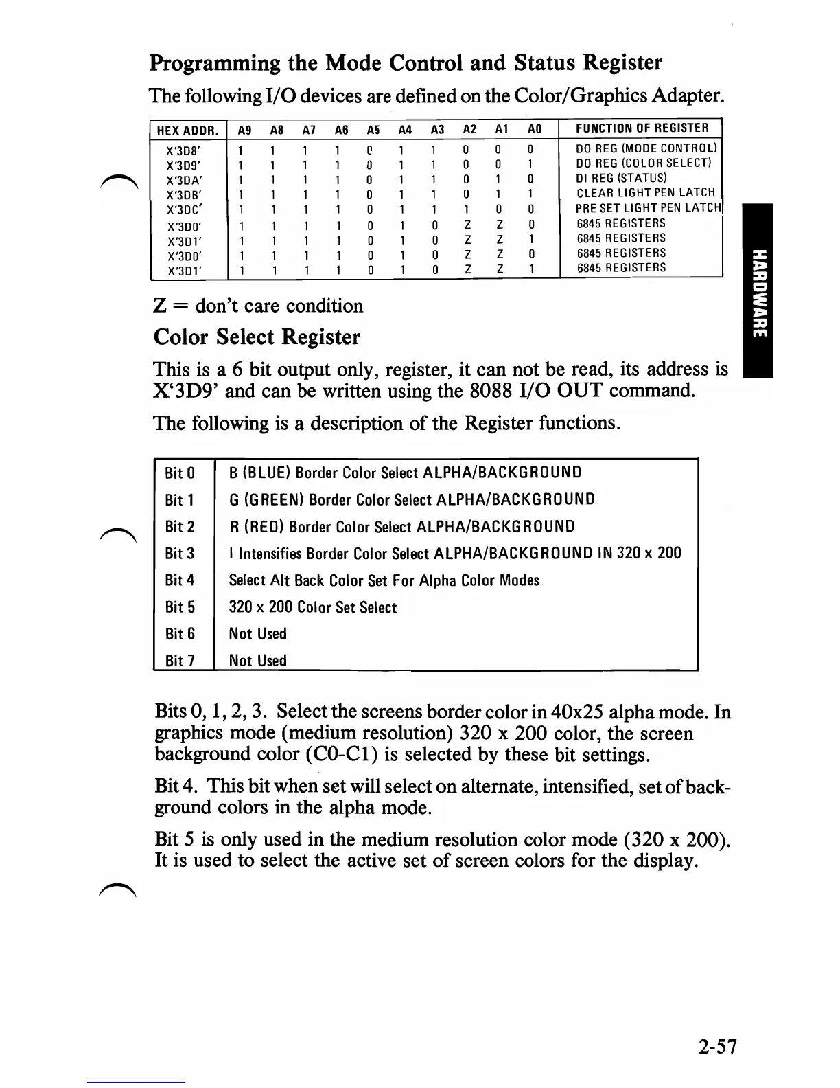
devices are defined on the Color/Graphics Adapter.
HEX
AOOR.
A9
A8 A7
A6 A5
A4
A3
A2
Al
AD
FUNCTION
OF
REGISTER
X'308' 1
1 1
1 0
1 1
0 0
0
DO
REG
(MODE
CONTROL)
X'309' 1 1
1
1 0 1
1 0
0
1
DO
REG
(COLOR
SELECT)
X'30A'
1 1 1
1 0
1 1
0
1 0
01
REG
(STATUS)
X'30B' 1 1
1 1
0
1 1 0
1
1
CLEAR
LIGHT
PEN
LATCH
X'30C'
1 1 1 1
0
1 1 1 0 0
PRE
SET
LIGHT
PEN
LATCH
X'300'
1 1 1 0
1 1 0
Z Z 0
6845
REGISTERS
X'301' 1
1 1 1 0
1 0
Z
Z
1
6845
REGISTERS
X'300'
1 1 1 1 0
1 0
Z
Z
0
6845
REGISTERS
X'301'
1 1 1 1 0
1 0
Z
Z
1
6845
REGISTERS
Z = don't care condition
Color Select Register
This
is
a 6 bit output only, register, it can not be read, its address
is
X'3D9'
and can be written using the 8088
I/O
OUT
command.
The following
is
a description
of
the Register functions.
Bit 0
B
(BLUE)
Border
Color
Select
ALPHA/BACKGROUND
Bit 1 G
(G
REEN)
Border
Color
Select
ALPHA/BACKG
RO
UNO
Bit
2
R
(RED)
Border
Color
Select
ALPHA/BACKGROUND
~
Bit 3
I
Intensifies
Border
Color
Select
ALPHA/BACKGROUND
IN
320
X
200
Bit 4
Select
Alt
Back
Color
Set
For
Alpha
Color
Modes
Bit 5
320
x
200
Color
Set
Select
Bit
6
Not
Used
Bit 7
Not
Used
Bits 0,
1,
2,
3.
Select the screens border color in 40x25 alpha mode. In
graphics mode (medium resolution) 320 x 200 color, the screen
background color (CO-Cl)
is
selected by these bit settings.
Bit 4. This bit when set will select on alternate, intensified, set
of
back-
ground colors in the alpha mode.
Bit 5
is
only used in the medium resolution color mode (320 x 200).
It
is
used to select the active set
of
screen colors for the display.
2-57

 Loading...


