Voltage
Interchange Information
Interface
Interchange
Voltage
Binary
State
Signal
Condition
Control
Function
Positive
Voltage
=
Binary
(0)
=
Spacing
=On
Negative
Voltage
=
Binary
(1)
=
Marking
=Off
Invalid
Levels
+15V-----------
On
Function
+3V
-----------
0\1 I
nvalid
Levels
-3V
-----------
Off
Function
-15V-----------
Invalid
Levels
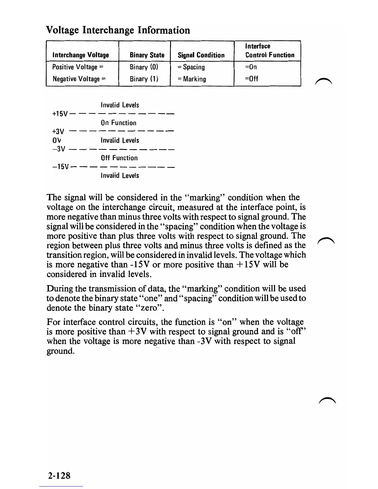
The signal will be considered in the "marking" condition when the
voltage
on
the interchange circuit, measured at the interface point,
is
more negative than minus three volts with respect to signal ground. The
signal will be considered in the "spacing" condition when the voltage is
more positive than plus three volts with respect to signal ground. The
region between plus three volts and minus three volts is defined as the
transition region, will be considered in invalid levels. The voltage which
is
more negative than -15V or more positive than +15V will be
considered in invalid levels.
During the transmission
of
data, the "marking" condition will be used
to denote the binary state
"one"
and "spacing" condition will be used to
denote the binary state
"zero".
For
interface control circuits, the function is
"on"
when the voltage
is
more positive than
+3V
with respect to signal ground and
is
"off"
when the voltage is more negative than -3V with respect to signal
ground.
2-128
 Loading...


