In the diagnostic mode, the receiver and transmitter interrupts are fully
operational. The
MODEM
Control Interrupts are also operational but
the interrupts' sources are now the lower four bits
of
the
MODEM
Control Register instead
of
the four
MODEM
Control inputs. The
interrupts are still controlled by the Interrupt Enable Register.
r--...
The
INS8250
interrupt system can be tested by writing into the lower
four bits
of
the
MODEM
Status Register. Setting any
of
these bits to a
logic 1 generates the appropriate interrupt (if enabled). The resetting
of
these interrupts is the same as in normal
INS8250
operation.
To
return
to normal operation, the registers must be reprogrammed for normal
operation and then bit 4
of
the
MODEM
Control Register must be reset
to logic
O.
Bits 5
through
7:
These bits are permanently set to logic
O.
MODEM StMus Register
This 8-bit register provides the current state ofthe control lines from the
MODEM
(or peripheral device) to the CPU.
In
addition to this current-
state information, four bits
of
the
MODEM
Status Register provide
change information. These bits are set to a logic 1 whenever a control
input from the
MODEM
changes state. They are reset to logic 0
whenever the
CPU
reads the
MODEM
Status Register.
~
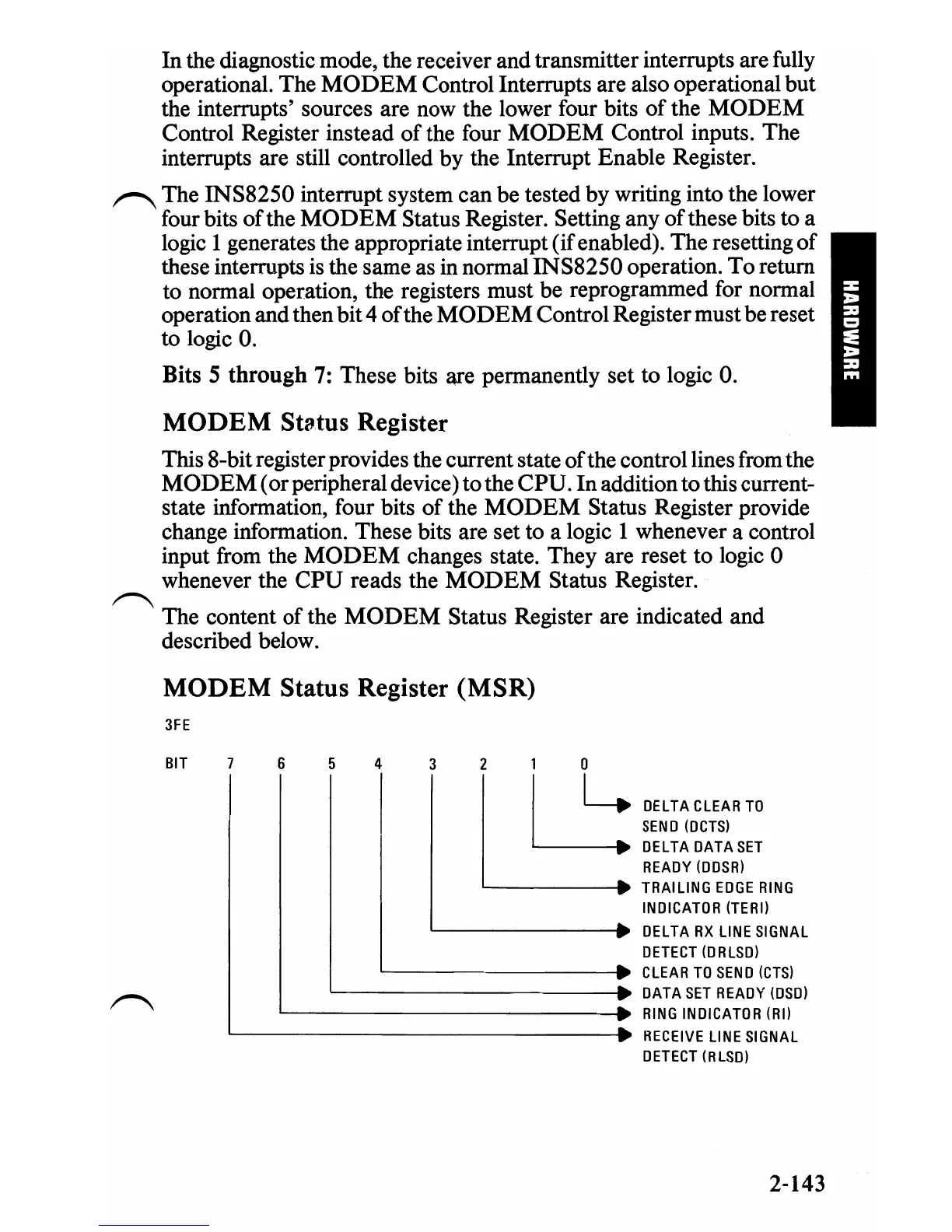
The content
of
the
MODEM
Status Register are indicated and
described below.
MODEM Status Register
(MSR)
3FE
BIT
6
5
4
3 2
1 0
DELTA
CLEAR
TO
I
SEND
WCTS)
DELTA
DATASET
READY
WDSR)
L----
____
• TRAILING
EDGE
RING
L::
INDICATOR
(TERI)
DELTA
RX
LINE
SIGNAL
OETECT
WRLSD)
CLEAR
TO
SEND
(CTS)
~------------;.~
DATA
SET
READY
(oSD)
'---------------.
RING
INDICATOR
(RI)
'-----------------.
RECEIVE
LINE
SIGNAL
DETECT
(RLSD)
2-143

 Loading...


