Speaker Interface
The sound system contains a small permanent magnet 2-1/4" speaker.
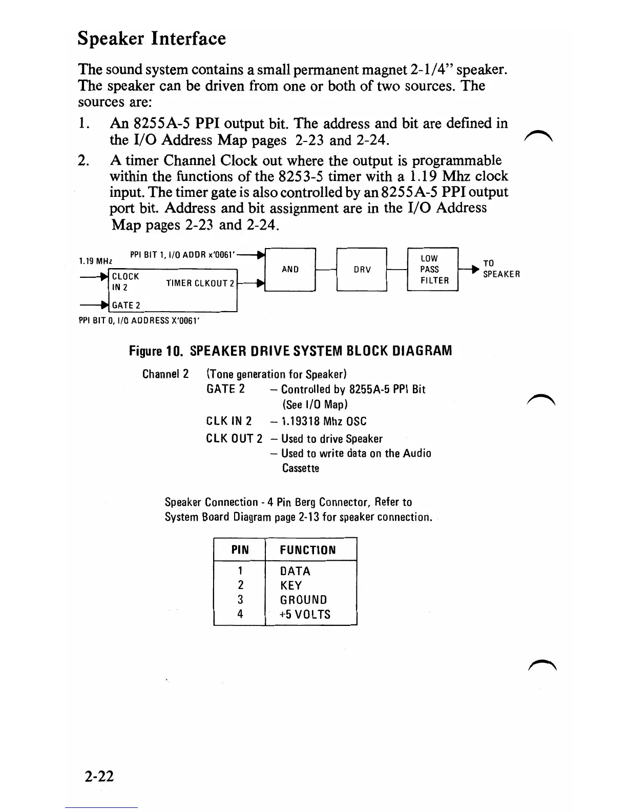
The speaker can be driven from one or both of two sources. The
sources are:
1.
An 8255A-5
PPI
output bit. The address and bit are defined in
the
I/O
Address Map pages 2-23 and 2-24.
~
2.
A timer Channel Clock out where the output
is
programmable
within the functions
ofthe
8253-5 timer with a 1.19 Mhz clock
input. The timer gate
is
also controlled by an 8255A-5 PPloutput
port bit. Address and bit assignment are
in
the
I/O
Address
Map pages 2-23 and 2-24.
PPI
BIT
1,1/0
ADDR
x'0061'
LOW
1.19
MHz
TO
,..--------,
AND
DRV
PASS
CLOCK
SPEAKER
TIMER
CLKOUT
2
FILTER
IN
2
PPI
BIT
0,
I/O
ADDRESS
X'0061'
Figure
10.
SPEAKER
DRIVE
SYSTEM
BLOCK
DIAGRAM
Channel
2
IT
one
generation
for
Speaker!
GATE
2 -
Controlled
by
8255A-5
PPI
Bit
(See
I/O
Map)
CLKIN2 -1.19318MhzOSC
CLK
OUT
2 -
Used
to
drive
Speaker
-
Used
to
write
data
on
the
Audio
Cassette
Speaker
Connection
-4
Pin
Berg
Connector,
Refer
to
System
Board
Diagram
page
2-13
for
speaker
connection.
PIN
FUNCTION
1
DATA
2
KEY
3
GROUND
4
+5
VOLTS
2-22

 Loading...


