MODEM
Control Register
This 8-bit register controls the interface with the
MODEM
or data set
(or a peripheral device emulating a MODEM). The contents of the
MODEM
Control Register are indicated and described below.
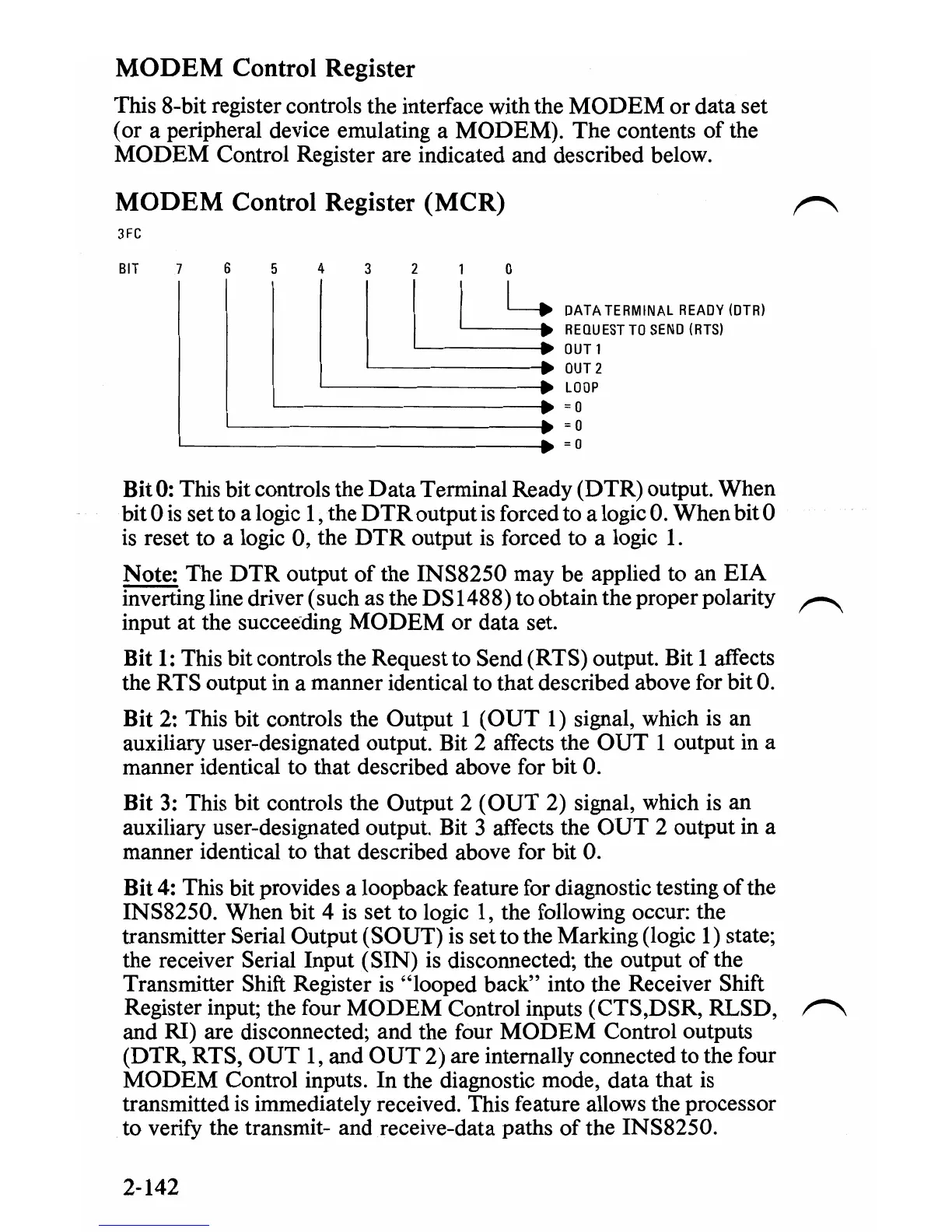
MODEM
Control Register (MCR)
3FC
BIT
6 5
43210
I
I.
_II
I~
IL
~:
DATA
TERMINAL
READY
IOTR!
.
L=;~
~~~~ESTTOSEND(RTS)
- OUT2
'---------
..
LOOP
~------------------~
L-
______________________
•
;0
;0
~------------------------__.
;0
Bit 0: This bit controls the
Data
Terminal Ready (DTR) output. When
bit 0
is
set to a logic
1,
the
DTR
output
is
forced to a logic
O.
When bit 0
is
reset to a logic 0, the
DTR
output
is
forced to a logic
1.
Note: The
DTR
output
of
the INS8250 may be applied to an
EIA
inverting line driver (such as the DS1488) to obtain the proper polarity
input at the succeeding
MODEM
or data set.
r"\
Bit
1:
This bit controls the Request to Send (RTS) output. Bit 1 affects
the RTS output in a manner identical to that described above for bit
O.
Bit 2: This bit controls the Output 1
(OUT
1)
signal, which
is
an
auxiliary user-designated output. Bit 2 affects the
OUT
1 output
in
a
manner identical to that described above for bit
O.
Bit
3:
This bit controls the Output 2
(OUT
2) signal, which
is
an
auxiliary user-designated output. Bit 3 affects the
OUT
2 output
in
a
manner identical to that described above for bit
O.
Bit
4:
This bit provides a loopback feature for diagnostic testing
of
the
INS8250. When bit 4
is
set to logic
1,
the following occur: the
transmitter Serial Output (SOUT)
is
set to the Marking (logic 1) state;
the receiver Serial Input (SIN)
is
disconnected; the output of the
Transmitter Shift Register
is
"looped back" into the Receiver Shift
Register input; the four
MODEM
Control inputs (CTS,DSR, RLSD,
and RI) are disconnected; and the four
MODEM
Control outputs
(DTR, RTS,
OUT
1,
and
OUT
2) are internally connected to the four
MODEM
Control inputs. In the diagnostic mode, data that
is
transmitted
is
immediately received. This feature allows the processor
to verify the transmit- and receive-data paths of the INS8250.
r"\
2-142

 Loading...


