Interrupt Enable Register
This 8-bit register enables the four types of interrupt of the INS8250
to separately activate the chip Interrupt (INTRPT) output signal.
It
is
possible to totally disable the interrupt system by resetting bits 0
through 3 of the Interrupt Enable Register. Similarly, by setting the
r'\
appropriate bits of this register to a logic 1, selected interrupts can be
enabled. Disabling the interrupt system inhibits the Interrupt Identi-
fication Register and the active (high)
INTRPT
output from the chip.
All other system functions operate
in
their normal manner, including
the setting of the Line Status and
MODEM
Status Registers. The
contents of the Interrupt Enable Register are indicated and
described below.
Interrupt Enable Register
(IER)
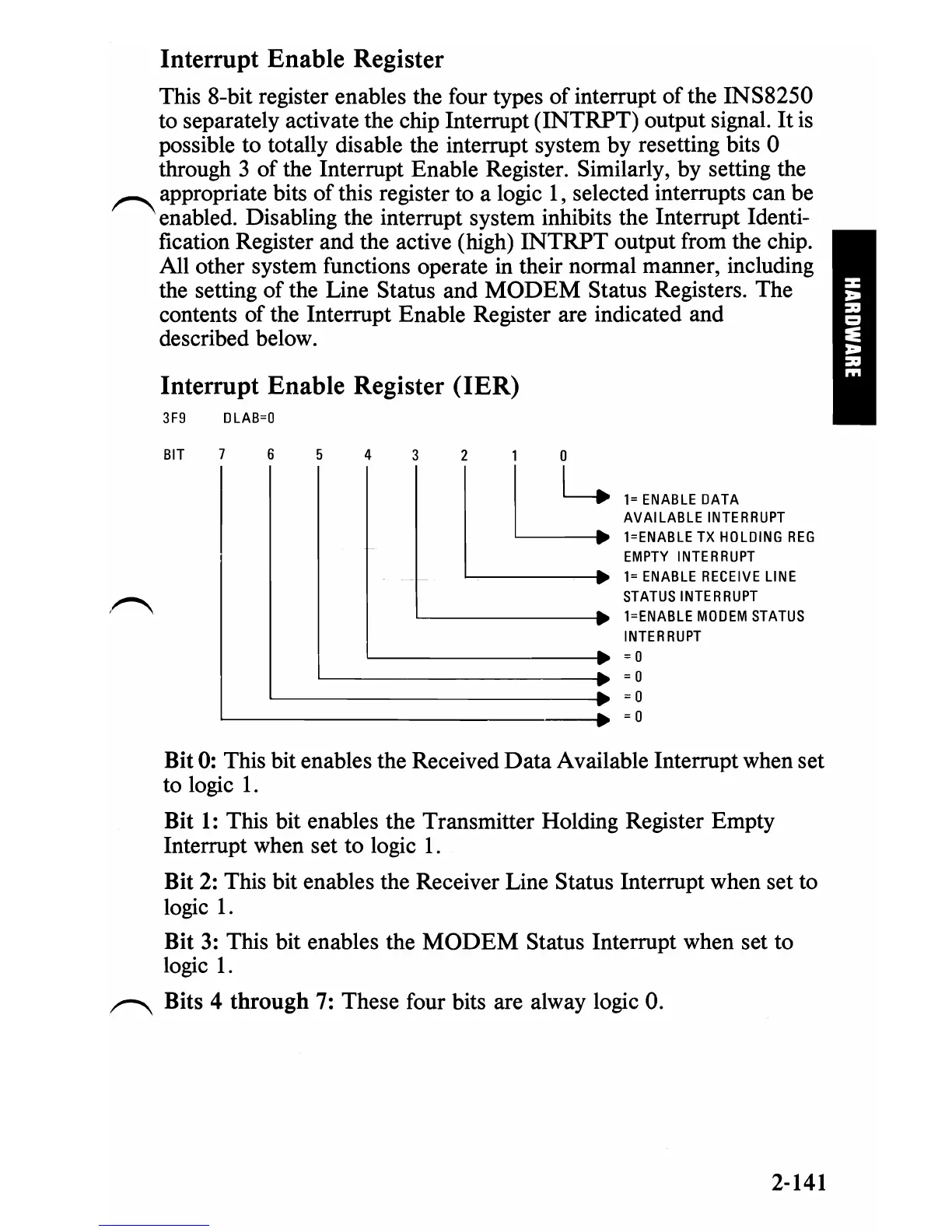
3F9
DLAB=O
BIT
7 6
4
3 1 0
1=
ENABLE
DATA
AVAILABLE
INTERRUPT
I=ENABLE
TX
HOLDING
REG
EMPTY
INTERRUPT
1=
ENABLE
RECEIVE
LINE
STATUS
INTERRUPT
I=ENABLE
MODEM
STATUS
INTERRUPT
p
=0
L::
~------------------
__
•
=0
=0
~----------------
__________
~.
=0
Bit
0:
This bit enables the Received
Data
Available Interrupt when set
to logic
1.
Bit
1:
This bit enables the Transmitter Holding Register Empty
Interrupt when set to logic
1.
Bit
2:
This bit enables the Receiver Line Status Interrupt when set to
logic
1.
Bit
3:
This bit enables the
MODEM
Status Interrupt when set to
logic
1.
r-"\
Bits 4 through
7:
These four bits are alway logic
O.
2-141

 Loading...


