System Board and Memory
Expansion Switch Settings
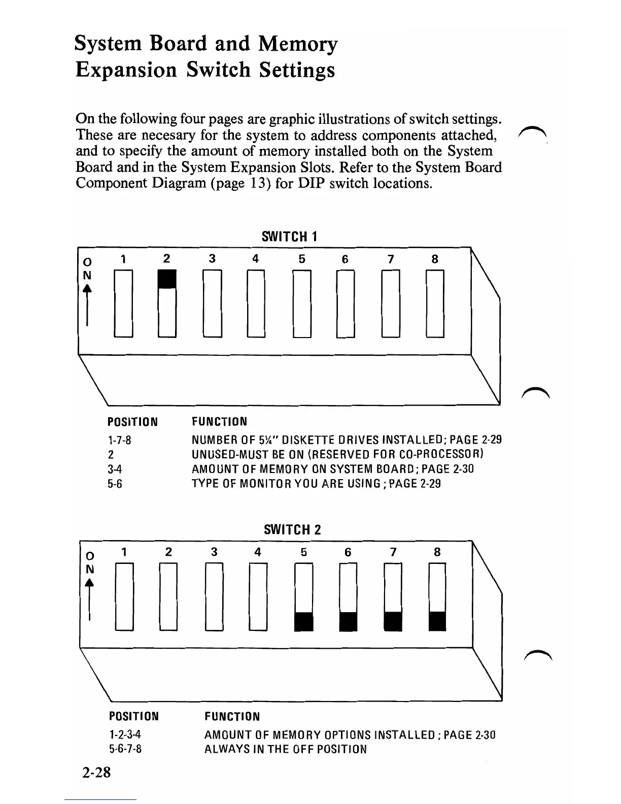
On the following four pages are graphic illustrations of switch settings.
These are necesary for the system to address components attached,
~
and to specify the amount
of
memory installed both on the System
Board and in the System Expansion Slots. Refer to the System Board
Component Diagram (page 13) for
DIP
switch locations.
SWITCH
1
o 1 2 3 4 5 6 7 8
1'\
rD~DDDDDD
POSITION
FUNCTION
1-7-8
NUMBER
OF
5%"
DISKETTE
DRIVES
INSTALLED;
PAGE
2-29
2
UNUSED-MUST
BE
ON
(RESERVED
FOR
CO-PROCESSOR)
3-4
AMOUNT
OF
MEMORY
ON
SYSTEM
BOARD;
PAGE
2-30
5-6
TYPE
OF
MONITOR
YOU
ARE
USING;
PAGE
2-29
SWITCH
2
o 1 2 3 4 5 6 7 8
1\
fDDDD~~~~
\
POSITION
FUNCTION
1-2-3-4
AMOUNT
OF
MEMORY
OPTIONS
INSTALLED;
PAGE
2-30
5-6-7-8
ALWAYS
IN
THE
OFF
POSITION
2-28

 Loading...


