Register Select (AO,
AI,
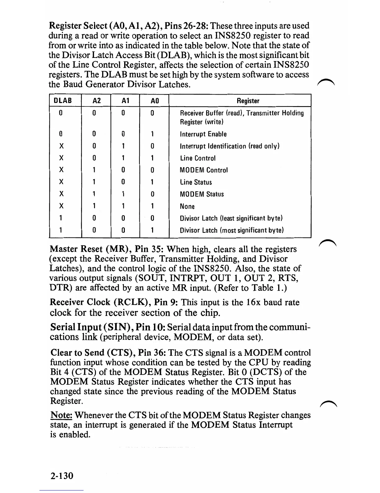
A2),
Pins
26-28: These three inputs are used
during a read or write operation to select an
INS8250
register to read
from or write into as indicated
in
the table below. Note that the state
of
the Divisor Latch Access Bit
(D
LAB), which is the most significant bit
of
the Line Control Register, affects the selection
of
certain INS8250
registers. The DLAB must be set high by the system software to access
the Baud Generator Divisor Latches.
DLAB
A2
A1
AD
Register
0
0 0 0
Receiver
Buffer
(read),
Transmitter
Holding
Register
(write)
0
0
0
1 Interrupt
Enable
X
0
1
0
Interrupt Identification
(read
only)
X
0
1
1
Li
ne
Co
ntrol
X 1
0
0
MODEM
Control
X 1
0
1
line Status
X 1 1
0
MODEM
Status
X 1 1
1
None
1
D 0
0
Divisor
Latch
(least
significant
byte)
1
D D 1
Divisor
Latch
(most
significant
byte)
Master
Reset
(MR),
Pin
35: When high, clears all the registers
(except the Receiver Buffer, Transmitter Holding, and Divisor
Latches), and the control logic
of
the INS8250. Also, the state
of
various output signals (SOUT, INTRPT,
OUT
1,
OUT
2, RTS,
DTR) are affected by an active
MR
input. (Refer to Table 1.)
Receiver
Clock
(RCLK),
Pin
9: This input
is
the
I6x
baud rate
clock for
the
receiver
section
of
the
chip.
Serial
Input
(SIN),
PintO:
Serial
data
input
from
the
communi-
cations
link (peripheral device,
MODEM,
or data set).
Clear
to
Send
(CTS),
Pin
36: The CTS signal
is
a
MODEM
control
function input whose condition can be tested by the
CPU
by reading
Bit
4 (CTS)
of
the
MODEM
Status Register. Bit 0
(DCTS)
of
the
MODEM
Status Register indicates whether the
CTS
input has
changed state since the previous reading
of
the
MODEM
Status
Register.
Note: Whenever the
CTS
bit ofthe
MODEM
Status Register changes
state, an interrupt is generated if the
MODEM
Status Interrupt
is enabled.
2-130
 Loading...


