Table 22. Behavior of system status LED of the utility node (continued)
LED type Color Behavior
LAN 1 and LAN 2 Green Off Offline.
Solid on Linking.
Blinking Access.
ID Blue Off Normal.
Solid on Located.
Warning Red Off System is working
normally.
On Indicates one or more of
the following:
• Memory warning
• PSU warning
• Fan warning
• System fault
M.2 SSD Green Blinking SSD activity.
Solid on An SSD is present.
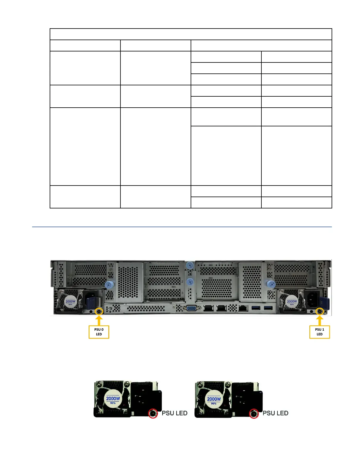
Power supply unit (PSU) LEDs
These LEDs on the rear of the enclosure are used to monitor the power supply units (PSUs) of the utility
node.
The following gure highlights the location of the status LEDs of PSU 0 and PSU 1.
Figure 50. PSU status LEDs of the utility node
Important: All PSUs must be AC on at the same time before you power on the system.
The PSUs have LEDs to indicate their status, as described in the following gure and table.
Figure 51. Close view of the PSU LEDs in the rear of the enclosure of the utility node
72
IBM Storage ScaleSystem Utility Node: Hardware Planning and Installation Guide
 Loading...