Table 23. PSU status LEDs on the rear of the utility node
PSU status LED color
2 PSU + 2 AC cords are installed when the system
power source is on.
Solid green.
1 PSU + 1 AC cord are installed when the system
power source is on.
1 + 1 PSU redundancy fail.
Solid green.
2 PSU + 2 AC cords are installed but after the
system starts operating normally, one of the PSUs
or AC cords is unplugged.
1 + 1 PSU redundancy fail.
Solid green turns into solid amber.
Ethernet port LEDs
The three onboard Ethernet ports of the utility node have LEDs that indicate speed and link activity.
These green and amber LEDs indicate the LAN status as described in the following tables.
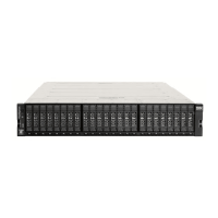
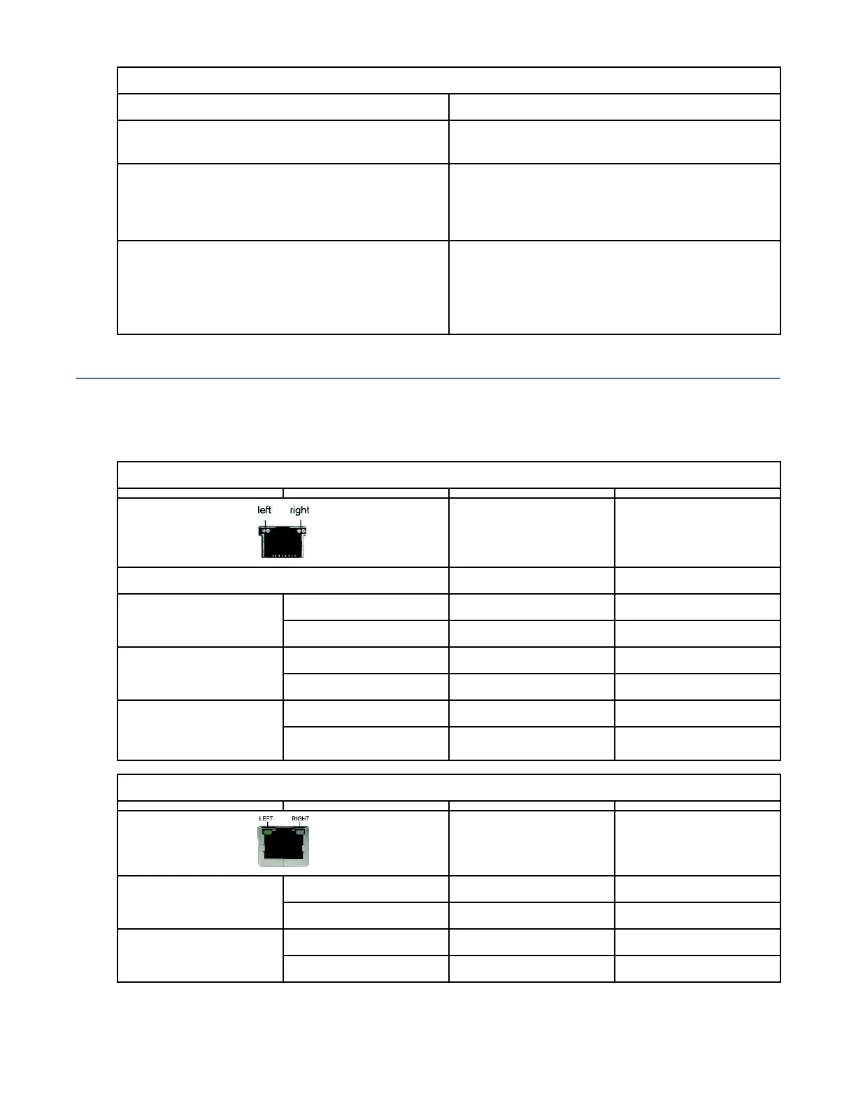
Note: The LAN port images that are included in the next tables are viewed from the rear panel.
Table 24. Link and activity LED scheme for the 10-Gbps LAN port
Left LED
(Link or activity)
Right LED
(Speed)
No link Off Off
100 Mbps Link Solid green Solid green
Active Blinking green Solid green
1000 Mbps Link Solid green Solid amber
Active Blinking green Solid amber
10,000 Mbps
(10 Gbps)
Link Solid amber Solid amber
Active Solid amber Solid amber
Table 25. Link and activity LED scheme for the 1-Gbps LAN port
Left LED Right LED
10 Mbps Link Solid green Off
Active Blinking green Off
100 Mbps Link Solid green Solid green
Active Blinking green Solid green
Chapter 5. Monitoring the system using LEDs73
 Loading...