FC compatibility
4, 8, 16 Gb
Cables
Cables are the responsibility of the customer. Use multimode ber optic cables with shortwave lasers
that adhere to the following specications:
• OM4: Multimode 50/125 micron ber, 4700 MHz x km bandwidth
• OM3: Multimode 50/125 micron ber, 2000 MHz x km bandwidth
• OM2: Multimode 50/125 micron ber, 500 MHz x km bandwidth
• OM1: Multimode 62.5/125 micron ber, 200 MHz x km bandwidth
Because core sizes are different, OM1 cables can only be connected to other OM1 cables. For best
results, OM2 cables must not be connected to OM3 cables. However, if an OM2 cable is connected to
an OM3 cable, the characteristics of the OM2 cable apply to the entire length of the cables.
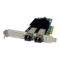
The following table shows the supported distances for the different cable types at the different link
speeds.
Table 32. Supported distances for cables
Header Cable type and distance
Rate OM1 OM2 OM3 OM4
4 Gbps 0.5 - 70 m (1.64 -
229.65 ft)
0.5 - 150 m (1.64
- 492.12 ft)
0.5 - 380 m (1.64
- 1246.71 ft)
0.5 - 400 m (1.64
- 1312.34 ft)
8 Gbps 0.5 - 21 m (1.64 -
68.89 ft)
0.5 - 50 m (1.64 -
164.04 ft)
0.5 - 150 m (1.64
- 492.12 ft)
0.5 - 190 m (1.64
- 623.36 ft)
16 Gbps 0.5 - 15 m (1.64 -
49.21 ft)
0.5 - 35 m (1.64 -
114.82 ft)
0.5 - 100 m (1.64
- 328.08 ft)
0.5 - 125 m (1.64
- 410.10 ft)
Adapter LED states
Green and yellow LEDs can be seen through openings in the mounting bracket of the adapter. Green
indicates rmware operation, and yellow signies port activity. Table 33 on page 176 summarizes normal
LED states. A 1 Hz pause occurs when the LED is off between each group of fast flashes (2, 3 or 4).
Observe the LED sequence for several seconds to ensure that you correctly identify the state.
Table 33. Normal LED states
Green LED Yellow LED State
On 2 fast flashes 4 Gbps link rate: normal, link
active
On 3 fast flashes 8 Gbps link rate: normal, link
active
On 4 fast flashes 16 Gbps link rate: normal, link
active
Power-on-self-test (POST) conditions and results are summarized in Table 34 on page 176. These states
can be used to identify abnormal states or problems.
Table 34. POST conditions and results
Green LED Yellow LED State
Off Off Wake-up failure of the adapter
board
176 Power Systems: Managing PCIe adapters