Slot requirement
For details about slot priorities, maximums, and placement rules, see PCIe adapter placement rules
and slot priorities (http://www.ibm.com/support/knowledgecenter/POWER9/p9eab/
p9eab_mtm_pciplacement.htm) and select the system you are working on.
Voltage
3.3 V
Form factor
Full-height, full-length adapter with standard-size bracket
FC compatibility
2, 4, and 8 gigabit FC devices
Cables
Cables are the responsibility of the customer. Use multimode bre optic cables with short-wave
lasers that adhere to the following specications:
• OM3: Multimode 50/125 micron bre, 2000 MHz x km bandwidth
• OM2: Multimode 50/125 micron bre, 500 MHz x km bandwidth
• OM1: Multimode 62.5/125 micron bre, 200 MHz x km bandwidth
Because core sizes are different, only OM1 cables can be connected to other OM1 cables. For best
results, do not connect OM2 cables to OM3 cables. However, if an OM2 cable is connected to an OM3
cable, the characteristics of the OM2 cable applies to the entire length of the cables.
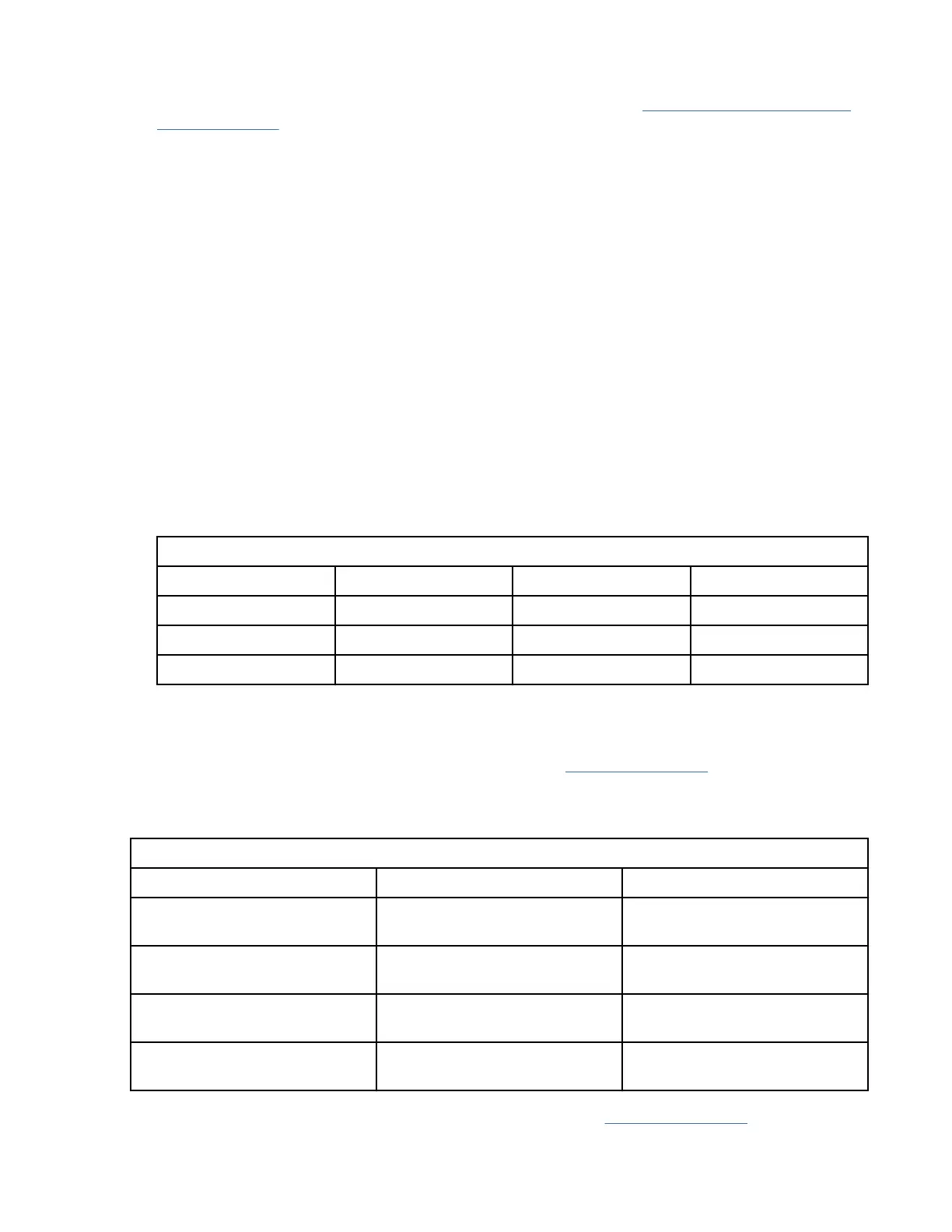
The following table shows the supported distances for the three different cable types at the three
different link speeds.
Table 16. Supported cable distances by link speed
Cable type 2.125 Gbps 4.25 Gbps 8.5 Gbps
OM3 0.5 m - 500 m 0.5 m - 380 m 0.5 m - 150 m
OM2 0.5 m - 300 m 0.5 m -150 m 0.5 m - 50 m
OM1 0.5 m - 150 m 0.5 m - 70 m 0.5 m - 21 m
Adapter LED
Green and yellow LEDs can be seen through openings in the mounting bracket of the adapter. Green
indicates rmware operation and yellow signies port activity. Table 17 on page 69 summarizes the link
rate conditions. There is a one second pause when the LED is off between each group of fast flashes (2, 3,
or 4). Observe the LED sequence for several seconds to be sure that you have correctly identied the
state.
Table 17. Normal LED states
Green LED Yellow LED State
Slow flashing Off Normal, link inactive or not
started
On 2 fast flashes 2 Gbps link rate - normal, link
active
On 3 fast flashes 4 Gbps link rate - normal, link
active
On 4 fast flashes 8 Gbps link rate - normal, link
active
Power-on self test (POST) conditions and results are summarized in Table 18 on page 70. These states
can be used to identify abnormal states or problems. Follow the action to be taken for each condition.
Managing PCIe adapters
69