MECHANICAL
AND
ELECTRICAL
PRINCIPLES
THE
REAR cover assembly and the covers on the right
and left ends of the machine are each held in place
by
means of concealed latches. These latches may
be
released
by
pressing on the latch cover plate.
The cover over the switch plate
is
hinged at the
bottom and held in place
by
a holding screw at the
upper right hand corner. The right end cover must
be removed before this holding screw
is
accessible.
Four adjustable levelers are furnished with each
machine for the purpose of leveling the machine and
to eliminate excessive vibration caused
by
an uneven
floor surface.
Chute Blades
and
Sort
Magnet
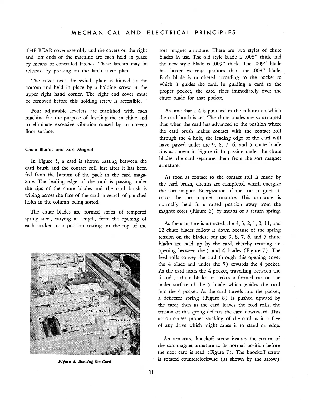
In
Figure 5, a card
is
shown passing between the
card brush and the contact roll just after it has been
fed
from the bottom of the pack in the card maga-
zine. The leading edge of the card
is
passing under
the tips of the chute blades and the card brush
is
wiping across the face of the card in search of punched
holes in the column being sorted.
The
chute blades are formed strips of tempered
spring steel, varying in length, from the opening of
each pocket to a position resting on the top of the
Fi~ure
5.
Sensin~
the
Card
11
sort magnet armature. There are two styles of chute
blades in
use.
The old style blade
is
.008" thick and
the new style blade
is
.009" thick. The .009" blade
has better wearing qualities than the
.008" blade.
Each blade
is
numbered according to the pocket to
which it guides the card.
In
guiding a card to the
proper pocket, the card rides immediately over the
chute blade for that pocket.
Assume that a 4
is
punched in the column on which
the card brush
is
set. The chute blades are
so
arranged
that when the card has advanced to the position where
the card brush makes contact with the contact roll
through the 4 hole, the leading edge of the card will
have passed under the 9, 8, 7, 6, and 5 chute blade
tips
as
shown in Figure
6.
In
passing under the chute
blades, the card separates them from the sort magnet
armature.
As
soon
as
contact
to
the contact roll
is
made
by
the card brush, circuits are completed which energize
the sort magnet. Energization of the sort magnet at-
tracts the sort magnet armature. This armature
is
normally held in a raised position away from the
magnet cores (Figure
6)
by
means
of
a return spring.
As the armature
is
attracted, the 4,
3,2,
1,
0,
11, and
12 chute blades follow it down because of the spring
tension
on
the blades; but the 9, 8, 7, 6, and 5 chute
blades are held up by the card, thereby creating an
opening between the 5 and 4 blades (Figure
7).
The
feed rolls convey the card through this opening (over
the 4 blade and under the
5)
towards the 4 pocket.
As
the card nears the 4 pocket, travelling between the
4 and 5 chute blades, it strikes a formed ear on the
under surface of the 5 blade which guides the card
into the 4 pocket.
As
the card travels into the pocket,
a deflector spring (Figure
8)
is
pushed upward by
the card; then
as
the card leaves the feed rolls, the
tension of this spring deflects the card downward. This
action causes proper stacking of the card
as
it
is
free
of any drive which might cause it to stand on edge.
An armature knockoff screw insures the return of
the sort magnet armature to its normal position before
the next card
is
read (Figure
7).
The
knockoff screw
is
rotated counterclockwise (as shown by the arrow)