16
CARD
SORTING
MACHINE,
TYPE
82
the main (outer) common ring. Note that
if
the zone
contact bar
is
in its retracted position, the digit com-
mon
is
not connected
to
the main common.
By
re-
tracting the zone contact bar, sorting of all digit values
1 through 9
is
suspended and only 0, 11, and 12 values
are sorted.
There are three division points
on
the periphery
of
the commutator; the inner, center, and outer rings.
Three contact brushes ride on this periphery, one to
contact each ring (Figure
11).
The inner ring con-
sists of
12
insulated segments corresponding to each
value in the card and internally connected to the 12
contact spots
as
mentioned above. The commutator
is
timed to the machine in such a manner that, when
the card brush makes through the 4 hole in the card
for example, the inner commutator brush will be mak-
ing contact
on
the 4 segment. The center and outer
rings are commoned together. The outer (common)
ring extends around the complete circumference
of
the commutator. The center ring extends around
approximately three fourths of the commutator cir-
cumference; the other one fourth
is
insulation.
When
a hole
is
sensed in the card, a circuit
to
fire
the
OA4G
trigger tube
is
first completed through the
commutator from one of the 12 segments on the inner
ring to the outer
or
common ring through the com-
mutator contact brushes and the contact bar for that
position.
As
soon as the trigger tube has been fired, a
holding circuit
to
maintain conduction in the tube
is
completed from the center brush
to
the outer brush.
Firing the trigger tube removes the negative bias
on
the sort magnet control tubes and allows them to
energize the
SOrt
magnet. Furnishing a hold circuit to
maintain conduction
in
the trigger tube keeps the sort
magnet energized until the center brush breaks con-
tact
on
the center ring. This occurs after the 12
position on the card has passed under the card
brush, thus completing the sensing of any holes
in
that card column.
If
two holes are present in a column being sensed,
and no provisions are made by means of the contact
bars
on
the commutator to suspend sorting
of
one
value, the card will sort according to the first value
sensed by the brush.
When
the reading brush
is
resting on the bare con-
tact roll between cards, no circuit
is
available to fire
the trigger tube because both the inner and center
commutator brushes are
on
insulated portions
of
the
commutator.
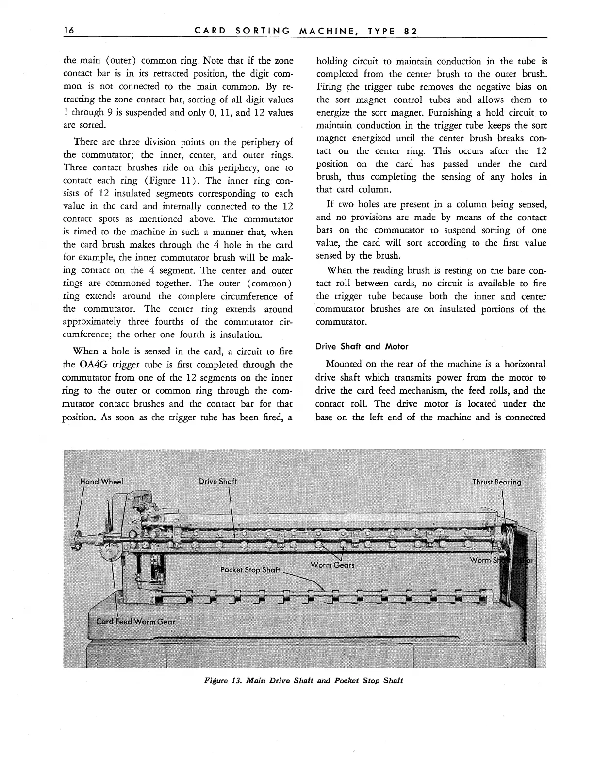
Drive Shaft and
Motor
Mounted
on
the rear of the machine
is
a horizontal
drive shaft which transmits power from the motor to
drive the card feed mechanism, the feed rolls, and the
contaot roll.
The
drive motor is
10C3Jted
under the
base
on
the left end
of
the machine and
is
connected
Figure
13.
Main
Drive
Shaft
and
Pocket
Stop
Shaft