IBM
978
CARD
COUNTING
UNIT
83
114-3
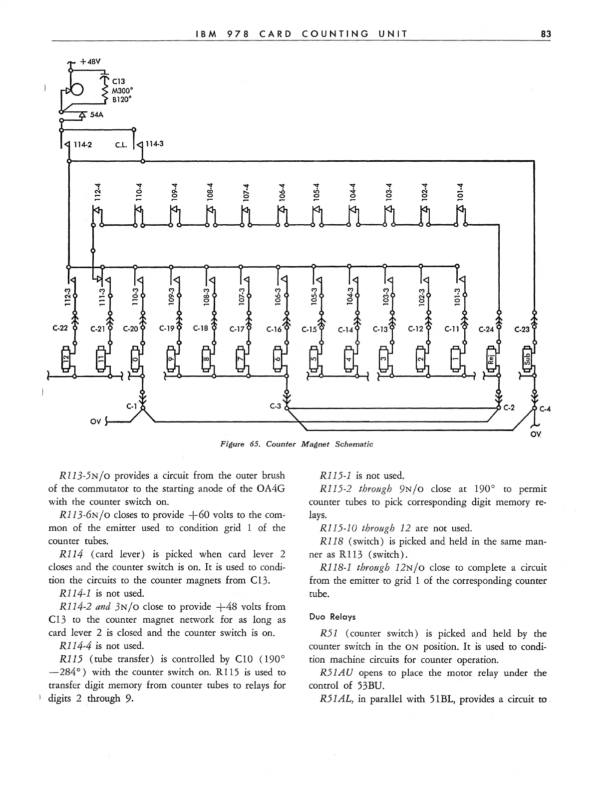
Figure 65.
Counter
Magnet
Schematic
R113-5N/O provides a circuit from the outer brush
of
the commutator to the starting anode of the OA4G
with the counter switch on.
R113-6N/o
closes to provide
+60
volts to the com-
mon of the emitter used to condition grid 1 of the
counter tubes.
R114 (card lever)
is
picked when card lever 2
closes and the counter switch
is
on.
It
is
used
to
condi-
tion the circuits
to
the counter magnets from C13.
R114-1
is
not used.
R114-2
and
3N/O close
to
provide
+48
volts from
C13
to
the counter magnet network for
as
long
as
card lever 2
is
closed and the counter switch
is
on.
Rl14-4
is
not used.
R115 (tube transfer)
is
controlled
by
C 1 0
(190
0
- 284
0)
with the counter switch on. R 115
is
used to
transfer digit memory from counter tubes to relays for
digits 2 through 9.
R115-1
is
not used.
R115-2 through 9N/O close at 190
0
to permit
counter tubes to pick corresponding digit memory
re-
lays.
Rl15-10
through 12 are not used.
Rl18
(switch)
is
picked and held in the same man-
ner
as
RI13
(switch).
Rl18-1
through 12N / 0 close to complete a circuit
from the emitter
to
grid 1 of the corresponding counter
tube.
Duo
Relays
R51
(counter switch)
is
picked and held
by
the
counter switch in the
ON
position.
It
is
used to condi-
tion machine circuits for counter operation.
R51AU
opens to place the motor relay under the
control of 53BU.
R51
AL,
in parallel with 51BL, provides a circuit to