18
CARD
SORTING
MACHINE,
TYPE
82
reverse lock
is
in the form of a ratchet knurl cut on the
rim of the drive pulley. A locking pawl operates against
the pulley when the force of motion
is
in a clockwise
direction (viewed from the pulley
end),
thus preventing
any actual rotation of the pulley.
When
the direction of
rotation
is
counterclockwise (viewed from the pulley
end),
the locking pawl
is
held away from the knurled
edge through the action of the pawl operating arm.
The pawl operating arm
is
actuated
by
a friction contact
with the drive pulley. The knurled teeth on the rim
of
the pulley are fine enough to prevent any appre-
ciable motion when the reverse lock operates. Any older
Type
80 machines which are not equipped with the
declutching type of handwheel should have a reverse
lock mechanism.
Feed
Knives
(Figures 16, 17, 17A)
The
feed
knives, in conjunction with the roller
throat assembly, are designed to feed one card at a
time from the card magazine. The roller throat
assem-
bly consists of a vertical knife whose lower edge
is
set parallel
to
a cylindrical steel roller. The throat
assembly
is
adjusted to allow the passage of only one
card at a time through an opening between the knife
. edge and the roller. The roller assembly
is
equipped
with small oil wicks for continuous lubrication.
Power to operate the
feed
knives
is
obtained from
the main drive shaft through the card
feed
worm gear
Figure
16.
Card
Magazine
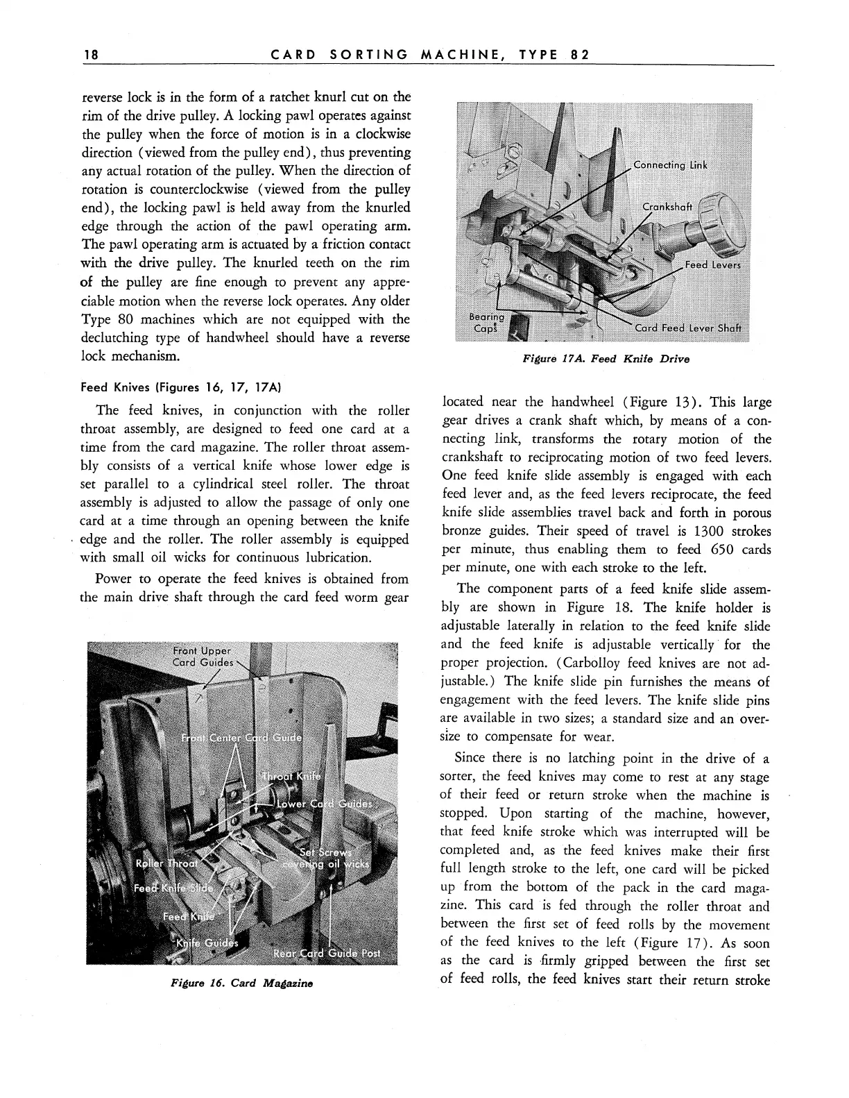
Figure
17A.
Feed
Knife
Drive
located near the handwheel (Figure
13).
This large
gear drives a crank shaft which,
by
means of a con-
necting link, transforms the rotary motion of the
crankshaft to reciprocating motion of two feed levers.
One feed knife slide assembly
is
engaged with each
feed
lever and,
as
the
feed
levers reciprocate, the
feed
knife slide assemblies travel back and forth in porous
bronze guides. Their speed of travel
is
1300 strokes
per minute, thus enabling them to feed
650 cards
per minute, one with each stroke to the left.
The component parts of
a feed knife slide
assem-
bly are shown in Figure 18. The knife holder
is
adjustable laterally in relation to the feed knife slide
and the
feed
knife
is
adjustable vertically' for the
proper projection. (Carbolloy
feed
knives are not
ad-
justable.) The knife slide pin furnishes the means of
engagement with the feed levers. The knife slide pins
are available in two
sizes;
a standard
size
and an over-
SIze
to
compensate for wear.
Since there
is
no latching point in the drive of a
sorter, the
feed
knives may come to rest at any stage
of their
feed
or return stroke when the machine
is
stopped. Upon starting of the machine, however,
that
feed
knife stroke which
was
interrupted will
be
completed and,
as
the
feed
knives make their first
full length stroke to the left, one card will be picked
up
from the bottom of the pack in the card maga-
zine. This card
is
fed
through the roller throat and
between the first set of
feed
rolls
by
the movement
of the feed knives to the left (Figure
17).
As
soon
as
the card
is
·firmly
gripped between the first set
of
feed
rolls, the
feed
knives start their return stroke