CIRCUIT
DESCRIPTION
37
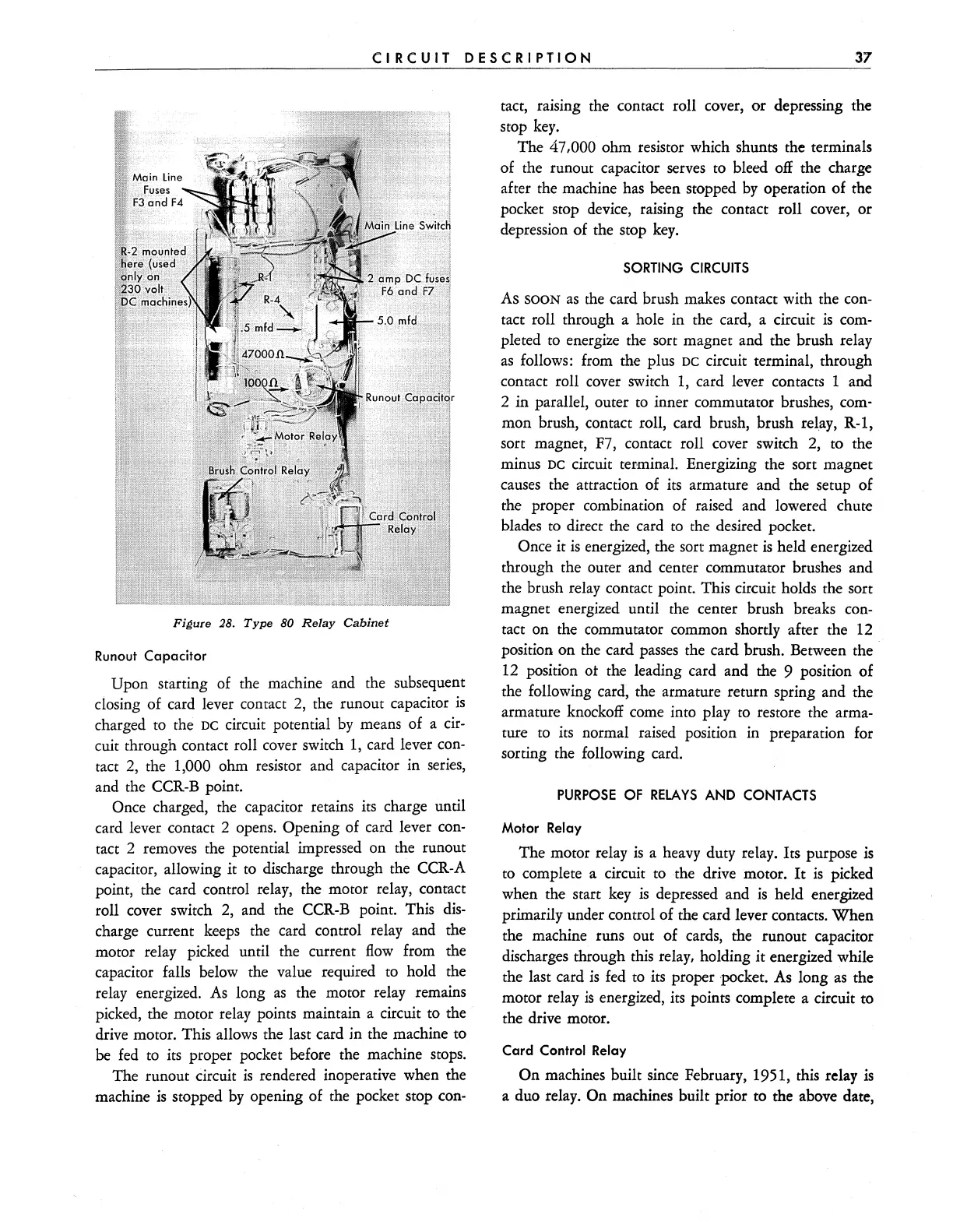
Fi~ure
28.
Type
80
Relay
Cabinet
Runout
Capacitor
Upon starting of the machine and the subsequent
closing of card lever contact
2,
the runout capacitor
is
charged to the DC circuit potential
by
means of a
cir-
cuit through contact roll cover switch
1,
card lever
con-
tact
2,
the 1,000 ohm resistor and capacitor in
series,
and the
CCR-B
point.
Once charged, the capacitor retains its charge until
card lever contact 2 opens.
Opening of card lever
con-
tact 2 removes the potential impressed on the runout
capacitor, allowing it
to
discharge through the
CCR-A
point, . the card control relay, the motor relay, contact
roll cover switch
2,
and the
CCR-B
point. This
dis-
charge current
keeps
the card control relay and the
motor relay picked until the current
flow
from the
capacitor falls below the value required to hold the
relay energized.
As
long
as
the motor relay remains
picked, the motor relay points maintain a circuit to the
drive motor. This allows the last card jn the machine to
be
fed
to
its proper pocket before the machine stops.
The runout circuit
is
rendered inoperative when the
machine
is
stopped
by
opening of the pocket stop
con-
tact, raising the contact roll cover, or depressing the
stop
key.
The 47,000 ohm resistor which shunts the terminals
of the runout capacitor
serves
to bleed
off
the charge
after the machine
has
been stopped
by
operation of the
pocket stop
device,
raising the contact roll cover, or
depression of the stop
key.
SORTING
CIRCUITS
As SOON
as
the
card brush makes contact with the
con-
tact roll through a hole in the card, a circuit
is
com-
pleted to energize the sort magnet and the brush relay
as
follows: from the plus DC circuit terminal, through
contact roll cover switch
1,
card lever contacts 1 and
2 in parallel, outer
to
inner commutator brushes,
com-
mon brush, contact roll, card brush, brush
rel.ay,
R-l,
sort magnet,
F7,
contact roll cover switch
2,
to the
minus
DC
circuit terminal. Energizing the sort magnet
causes
the attraction of
its
armature and the setup of
the proper combination of raised and lowered chute
blades
to
direct the card
to
the desired pocket.
Once it
is
energized, the sort magnet
is
held energized
through the outer and center commutator brushes and
the brush relay contact point. This circuit holds the sort
magnet energized until the center brush breaks
con-
tact on the commutator common shortly after the
12
position on the card
passes
the card brush. Between the
12
position ot the leading card and the 9 position of
the following card, the armature return spring and the
armature knockoff
come
into play
to
restore the arma-
ture to its normal raised position in preparation
for
sorting the following card.
PURPOSE
OF
RELAYS
AND
CONTACTS
Motor
Relay
The motor relay
is
a
heavy
duty relay. Its purpose
is
to
complete a circuit to the drive motor.
It
is
picked
when the start
key
is
depressed and
is
held energized
primarily under control of the card lever contacts. When
the machine runs out of cards, the runout capacitor
discharges through this relay, holding it energized while
the last card
is
fed
to its proper pocket.
As
long
as
the
motor relay
is
energized, its points complete a circuit to
the drive motor.
Card
Control Relay
On machines built
since
February, 1951, this relay
is
a duo relay. On machines built prior to the above date,