CIRCUIT
DESCRIPTION
ALL CIRCUITS described in the electrical principles of
the Type
75
Card Counting Sorter will refer to wiring
diagram
153129~S.
A reproduction of this wiring
dia-
gram
is
shown in Figure 32. Since the starting and run-
ning circuits in the Type
75
machine are very similar to
those employed in the Type
80 machine, they will not
be discussed in detail in this section of the manual.
Only the counting and sorting circuits will be covered.
The rectifier output voltage should be between
120 volts and 135 volts at the specified input voltage
(115,
200 or 230) with the machine stopped, and the
sort magnet and a count magnet energized.
NOTE:
The machine frame should
be
grounded.
However, it may be ungrounded at the customer's
op-
tion, except for 230 volt DC machines which must
be
grounded at all times.
No
point which can
be
touched
by
operating personnel can
be
hot when the switch
is
on and the frame
is
grounded.
Relay Cabinets and Power Supply Rectifier
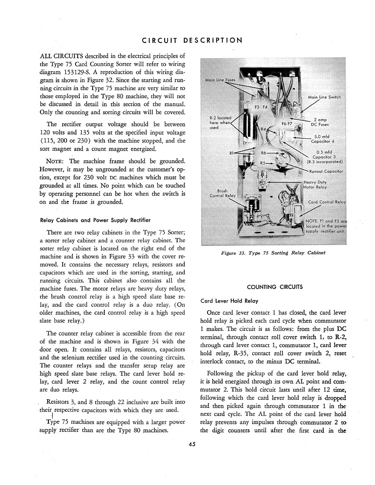
There are two relay cabinets in the Type
75
Sorter;
a sorter relay cabinet and a counter relay cabinet. The
sorter relay cabinet
is
located on the right end of the
machine and
is
shown in Figure
33
with the cover
re-
moved.
It
contains the necessary relays, resistors and
capacitors which are
use~
in the sorting, starting, and
running circuits. This cabinet also contains all the
machine
fuses.
The motor relays are heavy duty relays,
the brush control relay
is
a high speed slate
base
re-
lay, and the card control relay
is
a duo relay.
(On
older machines, the card control relay
is
a high speed
slate base relay.)
The counter relay cabinet
is
accessible from
the
rear
of the machine and
is
shown in Figure 34 with the
door
. open.
It
contains all relays, resistors, capacitors
and the selenium rectifier used in the counting circuits.
The counter relays and the transfer setup relay are
high speed slate base relays. The card lever hold
re-
lay, card lever 2 relay, and the count control relay
are duo relays.
Resistors
3,
and 8 through 22 inclusive are built into
. their respective capacitors with which they are
used.
,
Type
75
machines are equipped with a larger power
supply. rectifier than are the Type 80 machines.
45
Figure 33.
Type
75
Sorting
Relay
Cabinet
COUNTING
CIRCUITS
Card Lever Hold Relay
Once card lever contact 1 has closed, the card lever
hold relay
is
picked each card
cycle
when commutator
1 makes. The circuit
is
as
follows: from the plus
DC
terminal, through contact roll cover switch
1,
to R-2,
through card lever contact 1, commutator 1, card lever
hold relay, R-35, contact roll cover switch 2, reset
interlock contact, to the minus
DC
terminal.
Following the pickup of the card lever hold relay,
it
is
held energized through its own AL point and com-
mutator
2.
This hold circuit lasts until after 12 time,
following which the card lever hold relay
is
dropped
and then picked again through commutator 1 in the
next card
cycle.
The AL point of the card lever hold
relay prevents any impulses through commutator 2
to
the digit counters until after the first card in the