CARD
MATCHING
DEVICE
57
the advent of a detail card which again causes sorting
into the 9 pocket. Thus, it can be seen that if two
master cards occur in direct succession, the first master
card will follow its group of detail cards into the 9
pocket while the second master card will
be
rejected.
As
long
as
each master card
is
preceded
by
one or more
detail cards, both the detail cards and their master
card will sort into the 9 pocket.
If
it
is
desired
to
match a group of detail cards with
more than one master card, the master card identifica-
tion must occur only in the last master card of each
group.
If
the identifying punch or corner cut were
to
occur in all master cards, the first master card of each
group would
tollow its detail cards into the 9 pocket
but the latter master cards of the
group would be
re-
jected.
Cards which have no punching or no corner cut
which can be read
by
either the card brush or the rail
brush will
SOrt
into the same pocket
as
the preceding
card.
If
such a card
is
the first card fed into the machine,
it will reject.
Those cards having a corner cut or significant punch-
ing which
is
read
by
the card brush will reject, unless
they are preceded
by
a detail card.
The arrangement of the cards
as
well
as
the identify-
iRg
punching or corner cuts in the cards
is
a factor
that governs matching. However, it should
be
remem-
bered that matching with this device should
be
done
only with a master deck that
is
known to
be
complete.
CIRCUIT DESCRIPTION
THE
FOLLOWING
circuit description for card matching
covers the operation of a Type 82 Sorter with a card
matching device. The circuits described refer to wiring
diagram
270094. A reproduction of this wiring dia-
gram
is
shown in Figure 41.
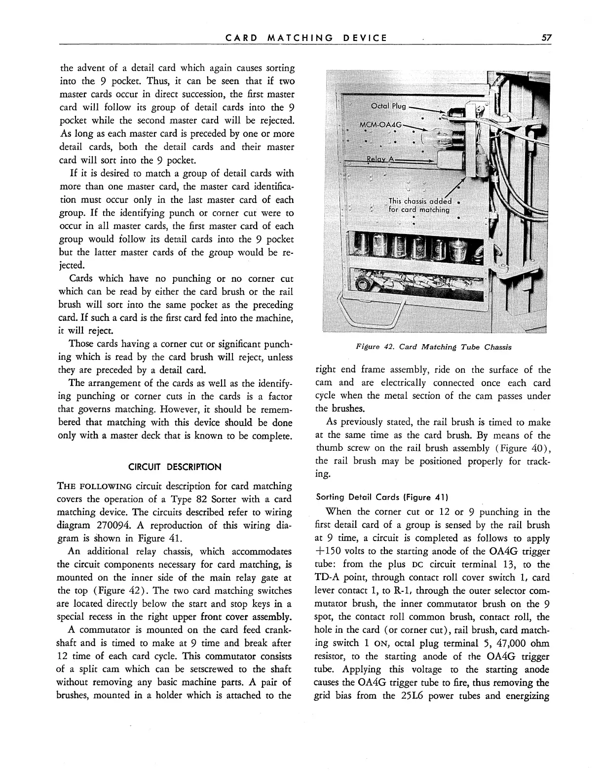
An additional relay chassis, which accommodates
the circuit components necessary for card matching,
is
mounted on the inner
side
of the main relay gate at
the top (Figure
42).
The two card matching switches
are located directly below the start and stop
keys
in a
special
recess
in the right upper front cover assembly.
A commutator
is
mounted on the card feed crank-
shaft and
is
timed
to
make at 9 time and break after
12 time of each card
cycle.
This commutator consists
of a split cam which can
be
setscrewed to the shaft
without removing any basic machine parts. A pair of
brushes, mounted in a holder which
is
attached to the
Figure
42.
Card
Matching
Tube
Chassis
right end frame assembly, ride on the surface of the
cam and are electrically connected once each card
cycle
when the metal section of the cam passes under
the brushes.
As
previously stated, the rail brush
is
timed
to
make
at the same time
as
the card brush.
By
means of the
thumb screw on the rail brush assembly (Figure
40),
the rail brush may
be
positioned properly for track-
ing.
Sorting
Detail
Cards
(Figure
41)
When the corner cut or 12 or 9 punching in the
first detail card of a group
is
sensed
by
the rail brush
at 9 time, a circuit
is
completed
as
follows to apply
+150
volts to the starting anode of the OA4G trigger
tube: from the plus
DC
circuit terminal 13, to the
TD-A point, through contact roll cover switch
1,
card
lever contact
1,
to
R-1,
through the outer selector com-
mutator brush, the inner commutator brush
on
the 9
spot, the contact roll common brush, contact roll, the
hole in the card (or corner
cut),
rail brush, card match-
ing switch
ION,
octal plug terminal
5,
47,000 ohm
resistor, to the starting anode of the
OA4G
trigger
tube. Applying
this voltage to the starting anode
causes
the OA4G trigger tube to
fire,
thus removing the
grid
bias from the 25L6 power tubes and energizing