M E C
HAN
I
CAL
AND
E L E C T R
IC
ALP
R
INC
I P L E S
21
in the reduction of any possible arcing
by
changing the
point of contact between the card brush and the contact
roll each card cycle.
The cutting effect of the card
is
more pronounced
at the first three feed roll stations than at any others.
For this reason, the rubber feed rolls at these stations
are equipped with metal flanges on either side of the
rubber rolls. These flanges serve to further prevent
knicking of the rubber rolls
by
deflecting the card
as
it strikes the roll. At the same time, because of
the position and diameter of the flanges, the rubber
portions of the rolls are permitted to exert pressure on
the card for feeding even though some wear has taken
place on the rubber rolls.
All feed roll gears are fastened to their
feed
roll
shafts
by
means of two setscrews through each gear
hub.
On recent machines, a hole
is
provided in the rear
magazine frame, permitting the entry of a setscrew
wrench to reach the setscrews in the first upper feed
roll gear.
Card
Levers
and Contacts (Figures 4, 19)
There are two card levers which operate
contact'S
to
govern machine circuits. Card lever 1 is located near
the
rear of the machine between the upper and lower
first
feed rolls and
is
operated
to
close
:its
contact just
as
the leading edge of the card enters the first feed rolIs.
Closing of card lever contact 1 allows the sorting
cir-
cuits
to
function if a hole
is
sensed in the card when it
passes under the card brush.
Card lever 2
is
located near the rear of the machine·
between the second and third upper feed rolls and
is
operated to close its contacts
as
the leading edge of the
card leaves the second feed roll. Closing of card lever
contact 2 governs two machine functions; one of which
is
to complete the circuits necessary for automatic
machine operation after the operator removes his finger
from the start
key.
The second function
is
to maintain
the sorting circuits during sorting of the last card in the
machine.
Once closed, the card lever contacts remain closed
during the time that cards are continuously feeding
through the machine, opening only when the machine
runs out of cards.
Pocket Stop Device
The pocket stop mechanism consists of a normally
closed contact operated
by
a lever (Figure
19).
This
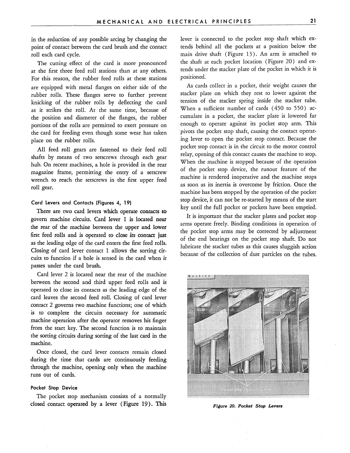
lever
is
connected to the pocket stop shaft which
ex-
tends behind all the pockets at a position below the
main drive shaft (Figure
13).
An arm
is
attached
to
the shaft at each pocket location (Figure
20)
and
ex-
tends under the stacker plate of the pocket in which it
is
positioned.
As cards collect in a pocket, their weight causes the
stacker plate on which they rest to lower against the
tension of the stacker spring inside the stacker tube.
When
a sufficient number of cards (450 to
550)
ac-
cumulate in a pocket, the stacker plate
is
lowered far
enough to operate against its pocket stop arm. This
pivots the pocket stop shaft, causing the contact
operat-
ing lever to open the pocket stop contact. Because the
pocket stop contact
is
in the circuit to the motor control
relay, opening of this contact causes the machine to stop.
When the machine
is
stopped because of the operation
of the pocket stop device, the runout feature of the
machine
is
rendered inoperative and the machine stops
as
soon
as
its
inertia
is
overcome
by
friction. Once the
machine has been stopped
by
the operation of the pocket
stop device,
it
can not be re-started
by
means of the start
key until the full pocket or pockets have been emptied.
It
is
important that the stacker plates and pocket stop
arms operate freely. Binding conditions in operation of
the pocket stop arms may be corrected
by
adjustment
of the end bearings on the pocket stop shaft.
Do
not
lubricate the stacker tubes
as
this causes sluggish action
because of the collection of dust particles on the tubes.
Fi~ure
:10.
Pocket
Stop
Levers