IBM
978
CARD
COUNTING
UNIT
79
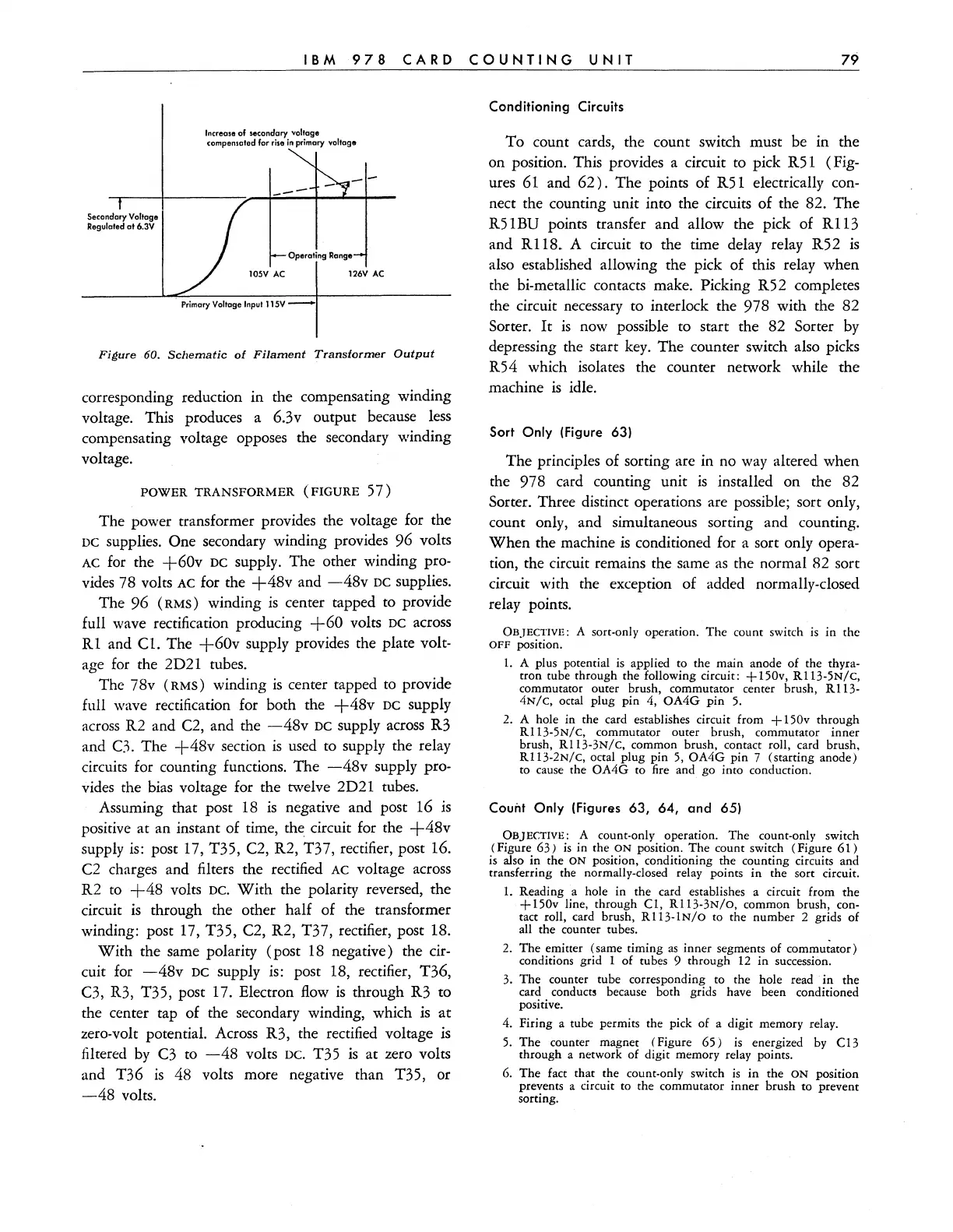
Secondary Voltage
Regulaled a16.3V
Increase
of secondary voltage
compensatod
for
rise
in
primary
voltage
--
Operating Range
10SV
AC
126V
AC
.
Primary
Voltage
Input
115V
~
Figure
60.
Schematic
of
Filament
Transformer
Output
corresponding reduction in the compensating winding
voltage. This produces a 6.3v output because
less
compensating voltage opposes the secondary winding
voltage.
POWER
TRANSFORMER
(FIGURE
57)
The power transformer provides the voltage for the
DC supplies. One secondary winding provides 96 volts
AC
for the
+60v
DC supply. The other winding pro-
vides 78 volts
AC
for the
+48v
and
-48v
DC supplies.
The
96
(RMS)
winding
is
center tapped to provide
full wave rectification producing
+60
volts DC across
R1
and
Cl.
The
+60v
supply provides the plate volt-
age for the 2D21 tubes.
The 78v
(RMS)
winding
is
center tapped to provide
full wave rectification for both the
+48v
DC
supply
across
R2 and C2, and the
-48v
DC supply
across
R3
and
C3. The
+48v
section
is
used to supply the relay
circuits for counting functions. The
-48v
supply pro-
vides the bias voltage for the twelve 2D21 tubes.
Assuming that post 18
is
negative and post 16
is
positive at an instant of time, the circuit for the
+48v
supply
is:
post 17, T35, C2, R2, T37, rectifier, post 16.
C2 charges and filters the rectified
AC voltage across
R2
to
+48
volts DC.
With
the polarity reversed, the
circuit
is
through the other half of the transformer
winding: post 17, T35, C2, R2, T37, rectifier, post 18.
With
the same polarity (post
18
negative) the
cir-
cuit for
-48v
DC supply is: post 18, rectifier, T36,
C3, R3, T35, post 17. Electron
flow
is
through R3 to
the center tap of the secondary winding, which
is
at
zero-volt potential. Across R3, the rectified voltage
is
filtered
by
C3
to
-48
volts DC. T35
is
at zero volts
and T36
is
48 volts more negative than T35, or
-48
volts.
Conditioning Circuits
To count cards, the count switch must be in the
on position. This provides a circuit to pick R51
(Fig-
ures
61
and
62).
The points of R51 electrically con-
nect the counting unit into the circuits of the 82. The
R5
1
BU
points transfer and allow the pick of R 113
and R118. A circuit to the time delay relay R52
is
also established allowing the pick of this relay when
the bi-metallic contacts make. Picking R52 completes
the circuit necessary to interlock the 978 with the 82
Sorter.
It
is
now possible to start the 82 Sorter
by
depressing the start
key.
The counter switch also picks
R54 which isolates the counter network while the
machine
is
idle.
Sort
Only
(Figure 63)
The principles of sorting are in no
way
altered when
the 978 card counting unit
is
installed on the 82
Sorter. Three distinct operations are possible; sort only,
count only, and simultaneous sorting and counting.
When
the machine
is
conditioned for a sort only opera-
tion, the circuit remains the same
as
the normal 82 sort
circuit with the exception of added normally-closed
relay points.
OBJECTIVE:
A sort-only operation.
The
count switch
is
in
the
OFF
position.
1.
A plus potential is applied to the main anode of the thyra-
tron tube through the following circuit: + 150v,
R1l3-5N/C,
commutator outer brush, commutator center brush, R113-
4N/C, octal plug pin 4,
OA4G
pin
5.
2. A hole in the card establishes circuit from
+150v
through
RI13-5N/C, commutator outer brush, commutator inner
brush,
RI13-3N/C, common brush, contact roll, card brush,
R1l3-2N/C, octal plug pin 5,
OA4G
pin 7 (starting anode)
to cause the
OA4G
to
fire and go into conduction.
Count
Only
(Figures 63, 64, and 65)
OBJECTIVE:
A count-only operation.
The
count-only switch
(Figure
63)
is
in the
ON
position.
The
count switch (Figure
61)
is also in the
ON
position, conditioning the counting circuits and
transferring the normally-closed relay points
in
the sort circuit.
1.
Reading a hole in the card establishes a circuit from
the
+150v
line, through
CI,
RI13-3N/O,
common brush, con-
tact roll, card brush,
RI13-1N/O
to
the number 2 grids of
all the counter tubes.
2.
The
emitter (same timing
as
inner segments of commutator)
conditions grid 1 of tubes 9 through 12
in
succession.
3.
The
counter tube corresponding to the hole read
in
the
card
conducts because both grids have been conditioned
positive.
4. Firing a tube permits the pick of a digit memory relay.
5.
The
counter magnet (Figure
65)
is energized by C13
through a network of digit memory relay points.
6.
The
fact that the count-only switch
is
in
the
ON
position
prevents a circuit to the commutator inner brush to prevent
sorting.