28
CARD
SORTING
MACHINE,
TYPE
82
SORT
MAGNET
r-
----
- - -
---,
1
---~I~~----------------~O~»~~--~
I
Rl.230V
DC
ONLY I
I
...
'
.. ..
..
...
I
.
v,,,
'V "
."
L
____________
J
+ 150
VOLTS
TO ANODES
AND
SCREEN
GRIDS
OF
25L6
TUBES
AND
ANODE
OF
OA4G
TUBE
~~
7
~,
'0'
oo"'oc'""
CONTACT
ROLL
COVER SWITCH 1
r------------,
RELAY
GATE
TERM.
13
I R4.230V
DC
ONLY I
I I
L
__
:.:.:
::'_'~:'~
__
-'
+ 150
VOLTS
o VOLTS TO
CATHODES OF
25L6
TUBES
OCTAL
PLUG
PINS
6&8
CONTACT
ROLL
COVER SWITCH 2
RECTIFIED
DC
SUPPLY
APPROXIMATELY 150 VOLTS
NO
LOAD
FOR
AC
OPERATION
(APPROX. 115 VOLTS
FOR
DC
OPERATION)
RELAY
GATE
TERM.
14
I
---~~------~~~----------~--~~~----------------~~~----------~
o---~O~VO~L~TS~---o
- ,
APPROX. -
40
VOLTS
BIAS
TO
CONTROL GRIDS OF
25L6
TUBES
AND
CATHODE
AND
START
ANODE
OF
OA4G
TUBE
INDUCED AC ACROSS
THIS
SECTION OF COIL
(GROUND
POTENTIAL)
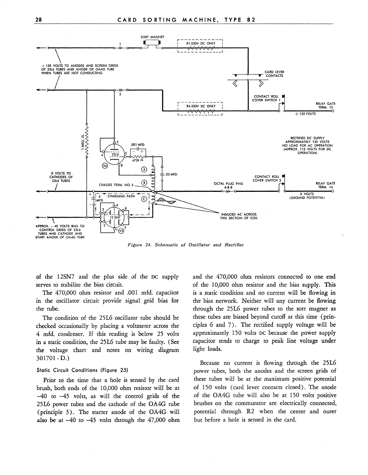
Figure 24.
Schematic
01
Oscillator
and
Rectifier
of
the 12SN7 and the plus
side
of the DC supply
serves
to
stabilize the bias circuit.
The
470,000 ohm resistor and .001 mfd. capacitor
in the oscillator circuit provide signal grid bias for
the rube.
The condition of the 25L6 oscillator tube should be
checked occasionally
by
placing a voltmeter
across
the
4 mfd. condenser.
If
this reading
is
below
25
volts
in a static condition, the 25L6 tube may be faulty. (See
the voltage chart and notes on wiring diagram
301701- D.)
Static Circuit Conditions (Figure 25)
Prior to the time that a hole
is
sensed
by
the card
brush, both ends of the
10,000 ohm resistor will be
at
-40
to
-45
volts,
as
will the control grids of the
25L6 power tubes and the cathode of the
OA4G tube
(principle
3).
The starter anode of the OA4G will
also be at
-40
to
-45
volts through the 47,000 ohm
and the
470,000 ohm resistors connected to one end
of the
10,000 ohm resistor and the bias supply. This
is
a static condition and no current will be flowing in
the bias network. Neither will
any
current be flowing
through the 25L6 power rubes to the sort magnet
as
these tubes are biased beyond cutoff at this time (prin-
ciples 6 and
7).
The rectified supply voltage will be
approximately
150 volts DC because the power supply
capacitor tends
to
charge
to
peak line voltage under
light loads.
Because
no
current
is
flowing through the 25L6
power tubes, both the anodes and the screen grids of
these tubes will be at the maximum positive potential
of
150 volts (card lever contacts closed). The anode
of the
OA4G tube will also be at 150 volts positive
brushes on the commutator are electrically connected,
potential through R2 when the center and outer
but before a hole
is
sensed in the card.