MECHANICAL
AND
ELECTRICAL
PRINCIPLES
13
Figure 8.
Cards
Entering the Pockets
and
is
mounted on the third lower feed roll shaft,
which
is
driven from the main worm shaft and makes
one revolution per card cycle.
It
is
timed
to
knock
off
the armature between the
12
position of one card
and the 9 position of the following card. Although
the return of the sort magnet armature
is
spring actu-
ated, the knockoff screw
is
provided to overcome any
residual magnetism present in the sort magnet.
If
the card fed
is
unpunched in the column being
sorted, the card brush fails
to
make contact with the
contact roll; therefore, the sort magnet
is
not ener-
gized and
its
armature
is
not attracted. Consequently,
the card
is
fed
under all the chute blades and deflected
into the R (reject) pocket.
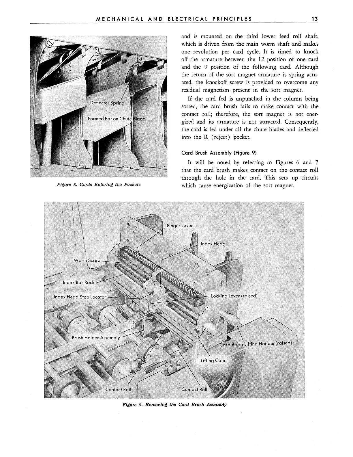
Card
Brush
Assembly (Figure
9)
It
will
be
noted
by
referring to Figures 6 and 7
that the card brush makes contact on the contact roll
through the hole in the card. This sets up circuits
which cause energization of the sort magnet.
Figure 9.
Removing
the Card Brush' Assembly