82
SPECIAL
DEVICES
I
9 !
• Grid # 1 from emitter,
See
note
0·"
Grid
#2
f~om
hole
in
card
:
Tube 9condiJcts
I
.....
~.
12
• Grid
247Wi
Grid
R115 Not
C----
fmI
_____
Eii!JCI3
112-3
~"'lIIiiiiiiiiiiiiiiiiiii_WJI
C 13
Read 9
Note: Emitter timing
and
inner
brush timing
are
identical
Read 12
Count 9
Count 12
Fi~ure
64.
Countin~
Operation
(Sequence
Chart)
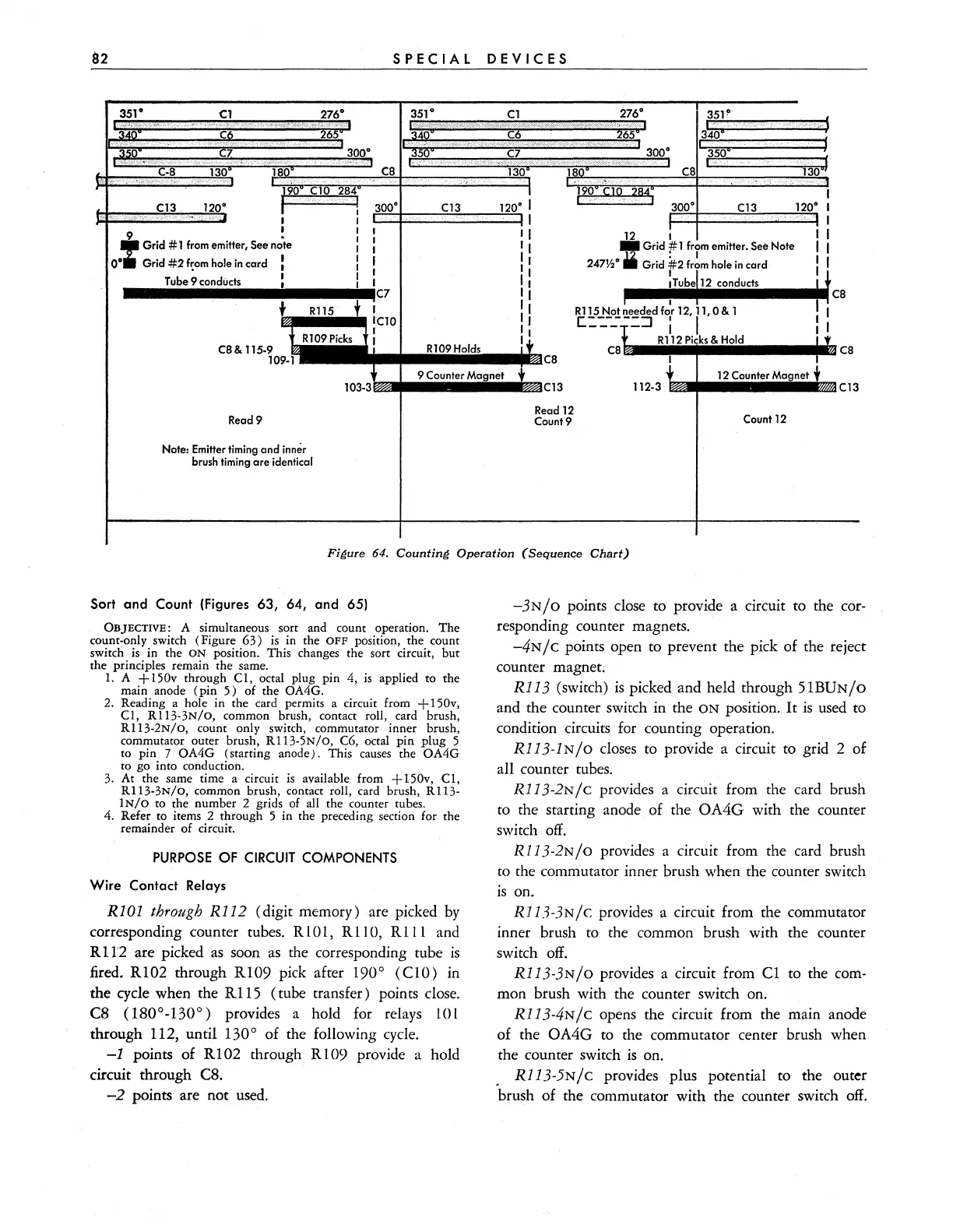
Sort and Count (Figures 63, 64, and 65)
OBJECTIVE:
A simultaneous sort and count operation. The
count-only switch (Figure
63)
is
in the
OFF
position, the count
switch
is
in the
ON
position. This changes the sort circuit,
but
the principles remain the same.
1.
A
+150v
through
CI,
octal plug pin 4,
is
applied to the
main anode (pin
5)
of the OA4G.
2.
Reading a hole in the card permits a circuit from
+150v,
CI,
RI13-3N/o,
common brush, contact roll, card brush,
R113-2N/O, count only switch, commutator inner brush,
commutator outer brush, RI13-5N/O, C6, octal pin plug 5
to pin 7
OA4G (starting anode). This
causes
the OA4G
to go into conduction.
3.
At the same time a circuit
is
available from + 150v,
CI,
R113-3N/O, common brush, contact roll, card brush,
RI13-
IN/O
to the number 2 grids of all the counter tubes.
4. Refer to items 2 through 5 in the preceding section for the
remainder
of
circuit.
PURPOSE
OF
CIRCUIT
COMPONENTS
Wire
Contact Relays
RIOI
through R112 (digit memory) are picked
by
corresponding counter tubes. R L 0
L,
R 110, R 1 L 1 and
Rl1'2 are picked
as
soon
as
the corresponding tube
is
fired_
R I 02 through R 109 pick after 190 ° ( C 10) in
the cycle when the
RII5
(tube transfer) points close.
C8
(180
0
-130
0
)
provides a hold for relays
LOL
through 112, until 1300 of the following cycle.
-1
points of
RI02
through R109 provide a hold
circuit through C8.
-2
points are not used.
-3NjO
points close to provide a circuit to the cor-
responding counter magnets_
-4N j C points open to prevent the pick of the reject
counter magnet.
RI13
(switch)
is
picked and held through 5 I
BUNjO
and the counter switch in the
ON
position.
It
is
used to
condition circuits for counting operation.
RI13-1NjO
closes to provide a circuit to grid 2 of
all counter tubes.
R113-2Njc
provides a circuit from the card brush
to the starting anode of the
OA4G with the counter
switch
off_
R
11
3 -2N j 0 provides a circuit from the card brush
to the commutator inner brush when the counter switch
is
on_
R113-3NjC provides a circuit from the commutator
inner brush to the common brush with the counter
switch
off_
R113-3NjO provides a circuit from
CI
to the com-
mon brush with the counter switch on.
R113-4Njc
opens the circuit from the main anode
of the
OA4G to the commutator center brush when
the counter switch
is
on.
. R113-5NjC provides plus potential to the outer
brush of the commutator with the counter switch
off.