SPECIAL
DEVICES
AUXILIARY
CARD
COUNTING
DEVICE
THE AUXILIARY card counting device on the Type
80 or Type 82 Sorter
is
a device for counting all cards
which pass through the machine. The counter on the
Type 82 operates at
650 cards per minute and the
counter on the Type
80 operates at 450 cards per
minute. They are not interchangeable. The principles
of operation and the circuits described in the following
paragraphs apply primarily
to
the high speed auxiliary
card counter which
is
available on the Type 82 Sorter.
The circuits for the card counter on the Type 80 are
very similar to those on the Type 82. The mechanical
principles for the counter on the Type
80 are described
under
Card
Counters, in the Type
75
section of this
manual.
When
used
as
an auxiliary card counter on a
Type
80 machine, the counter shown in Figure 30 has
a manual reset knob in place of the reset gear shown.
The auxiliary card counter
does
not affect machine
speed and all normal functions may be performed,
re-
gardless of the position of the card count switch. The
capacity of the counter
is
99,999, and it may be reset
to
00,000
by
turning the knurled hand wheel. The
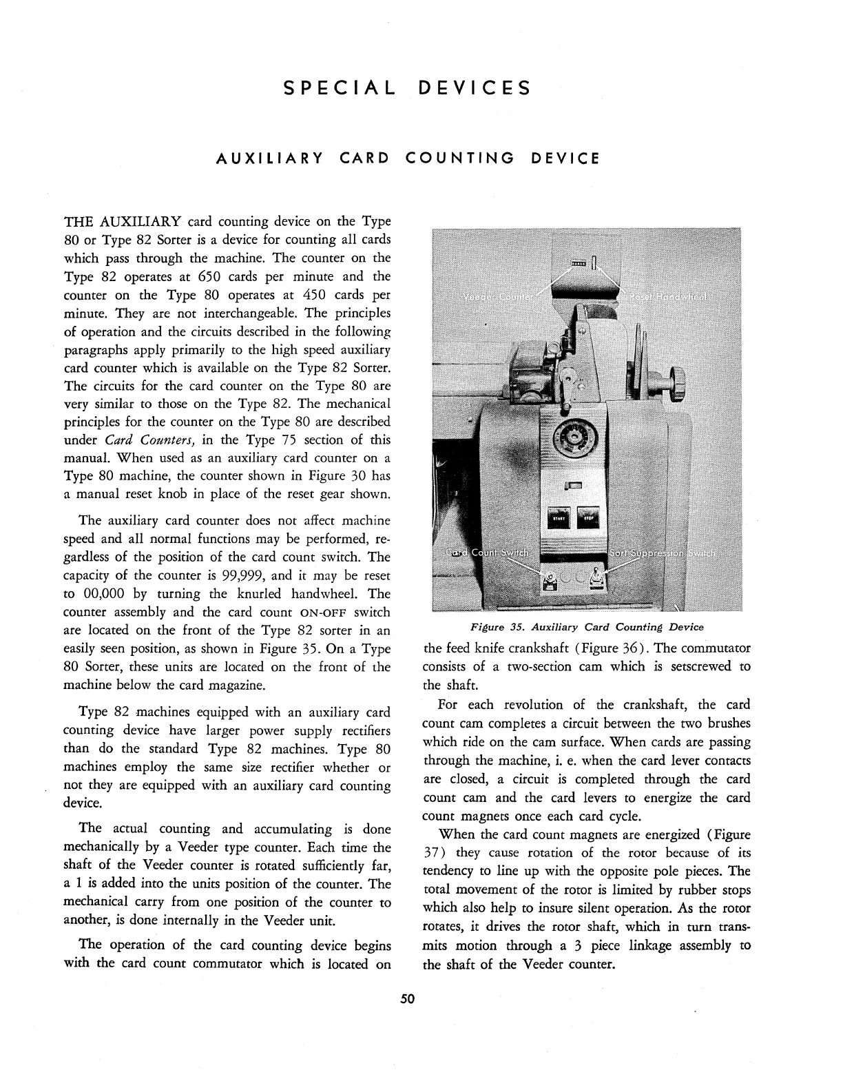
counter assembly and the card count
ON-OFF
switch
are located on the front of the Type 82 sorter in an
easily seen position,
as
shown
in
Figure 35. On a Type
80 Sorter, these units are located on the front of the
machine below the card magazine.
Type 82 machines equipped with an auxiliary card
counting device have larger power supply rectifiers
than do the standard Type 82 machines. Type
80
machines employ the same
size
rectifier whether or
not they are equipped with an auxiliary card counting
device.
The actual counting and accumulating
is
done
mechanically by a Veeder type counter. Each time the
shaft of the Veeder counter
is
rotated sufficiently far,
a 1
is
added into the units position of the counter. The
mechanical carry from one position of the counter to
another,
is
done internally in the Veeder unit.
The operation of the card counting device begins
with the card count commutator which
is
located on
50
Fiaure 35.
Auxiliary
Card
Countina
Device
the
feed
knife crankshaft (Figure
36).
The commutator
consists of a two-section cam which
is
setscrewed to
the shaft.
For each revolution of the crankshaft, the card
count cam completes a circuit between the two brushes
which ride on the cam surface.
When
cards are passing
through the machine, i.
e.
when the card lever contacts
are closed, a circuit
is
completed through the card
count cam and the card levers
to
energize the card
count magnets once each card cycle.
When
the card count magnets are energized (Figure
37)
they cause rotation of the rotor because of its
tendency
to
line up with the opposite pole pieces. The
total movement of the rotor
is
limited
by
rubber stops
which also help to insure silent operation.
As
the rotor
rotates, it drives the rotor shaft, which in turn trans-
mits motion through a 3 piece linkage assembly to
the shaft of the Veeder counter.