A U X
IL
I A R Y
CAR.
D C 0 U
NT
I N G D E V
ICE
51
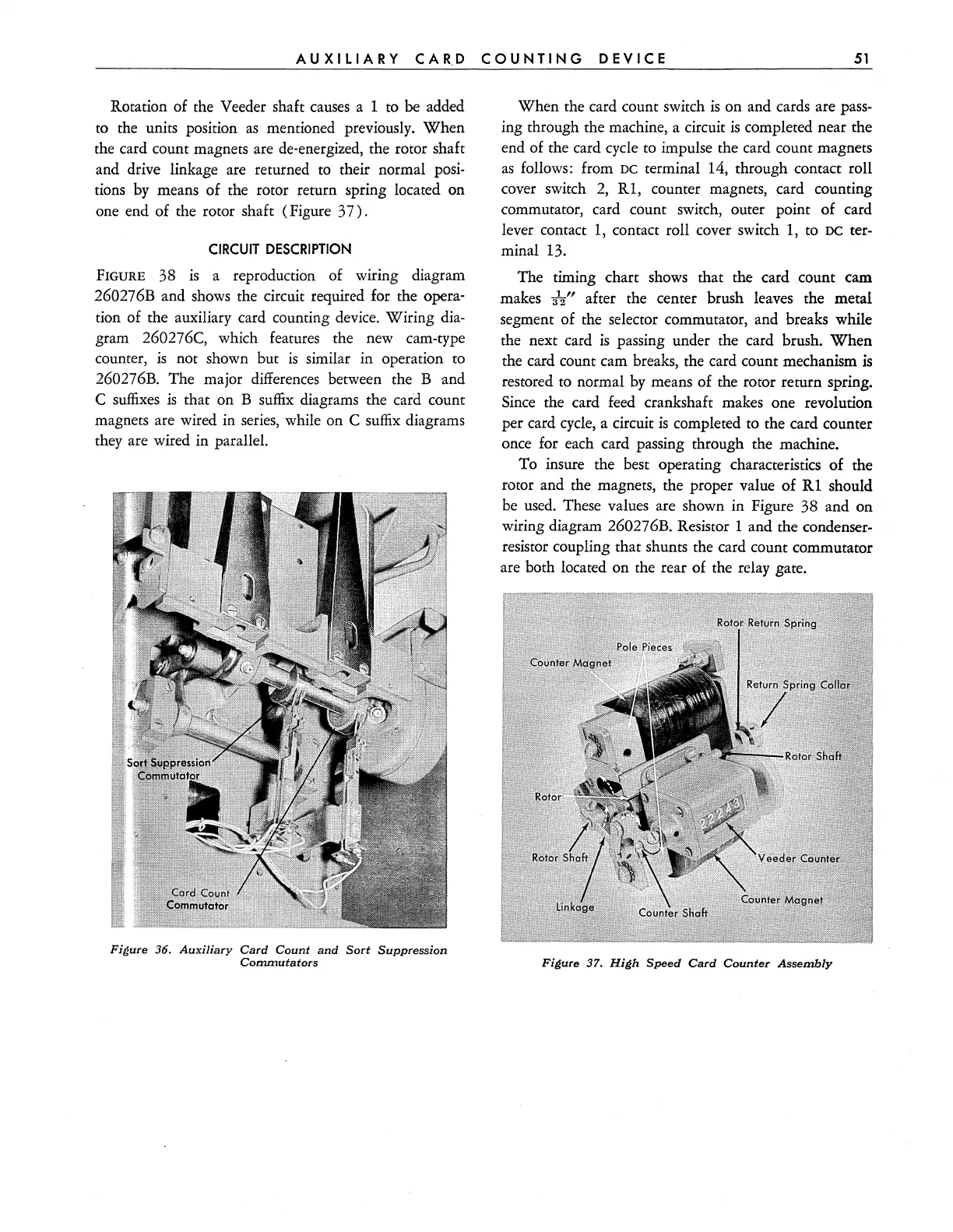
Rotation of the Veeder shaft
causes
a 1 to
be
added
to
the units position
as
mentioned previously.
When
the card count magnets are de-energized, the rotor shaft
and drive linkage are returned
to
their normal
posi-
tions
by
means of the rotor return spring located on
one end of the rotor shaft (Figure
37).
CIRCUIT
DESCRIPTION
FIGURE
38
is
a reproduction of wiring diagram
260276B and shows the circuit required for the opera-
tion of the auxiliary card counting device. Wiring dia-
gram 260276C, which features the new cam-type
counter,
is
not shown but
is
similar in operation to
260276B. The major differences between the
Band
C
suffixes
is
that on B
suffix
diagrams the card count
magnets are wired in series, while on C
suffix
diagrams
they are wired in parallel.
Figure 36.
Auxiliary
Card
Count
and
Sort
Suppression
Commutators
When the card count switch
is
on and cards are pass-
ing through the machine, a circuit
is
completed near the
end of the card cycle
to
impulse the card count magnets
as
follows: from DC terminal 14, through contact roll
cover switch
2,
Rl,
counter magnets, card counting
commutator, card count switch, outer point of card
lever contact
1,
contact roll cover switch 1,
to
DC
ter-
minal 13.
The timing chart shows that the card count cam
makes
3V'
after the center brush
leaves·
the metal
segment of the selector commutator, and breaks while
the next card
is
passing under the card brush.
When
the card count cam breaks, the card count mechanism
is
restored to normal
by
means of the rotor return spring.
Since
the card feed crankshaft makes one revolution
per card
cycle,
a circuit
is
completed
to
the card counter
once for each card passing through the machine.
To insure the best operating characteristics
of
the
rotor and the magnets, the proper value of
Rl
should
be
used.
These values are shown in Figure 38 and on
wiring diagram
260276B. Resistor 1 and the condenser-
resistor coupling that shunts the card count commutator
are both located on the rear of the relay gate.
Figure 37.
High
Speed
Card
Counter
Assembly