MECHANICAL
AND
ELECTRICAL
PRINCIPLES
17
to the drive shaft
by
means of a V belt and pulleys.
Variations in machine speed are obtained
by
adjusting
the variable speed pulley on the drive motor. The
motor mounting
is
adjustable vertically and can be
pivoted in an arc for the purpose of regulating belt
tension and alignment. The complete motor and
mounting assembly
is
easily removed for repair or
renewal.
The drive shaft extends over the length of the
machine approximately on a level with the card line
(Figure
13).
Worms cut at intervals on the shaft
are used for the purpose of gearing to the
feed
roll
shafts, which run at right angles to the drive shaft.
Except for the first 3
sets
of feed rolls, only the lower
feed rolls are gear driven; the upper rolls are friction
driven from the lower rolls. Located at the right end
of the drive shaft (rear view)
is
a thrust bearing which
aids in absorbing the thrust developed in the shaft.
This bearing must be kept well lubricated.
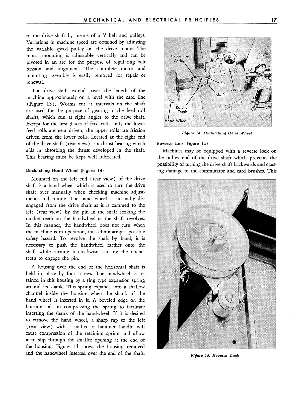
Declutching Hand Wheel (Figure 14)
Mounted on the left end (rear view) of the drive
shaft
is
a hand wheel which
is
used
to turn the drive
shaft over manually when checking machine adjust-
ments and timing. The hand wheel
is
normally
dis-
engaged from the drive shaft
as
it
is
cammed
to
the
left (rear view)
by
the pin in the shaft striking the
ratchet teeth on the handwheel
as
the shaft revolves.
In
this manner, the handwheel
does
not turn when
the machine
is
in operation, thus eliminating a possible
safety hazard. To revolve the shaft
by
hand, it
is
necessary to push the handwheel farther onto the
shaft while turning it clockwise, causing the ratchet
teeth to engage the pin.
A housing over the end of the horizontal shaft
is
held in place
by
four
screws.
The handwheel
is
re-
tained in this housing
by
a ring type expansion spring
around its shank. This spring expands into a shallow
channel inside the housing when the shank of the
hand wheel
is
inserted in it. A beveled edge on the
housing
aids
in compressing the spring to facilitate
inserting the shank of the handwheel.
If
it
is
desired
to remove the hand wheel, a sharp rap to the left
(rear view) with a mallet or hammer handle will
cause compression of the retaining spring and allow
it to slip through the smaller opening at the end of
the housing. Figure 14 shows the housing removed
and the handwheel inserted over the end
of
the shaft.
Figure 14.
Declutching
Hand
Wheel
Reverse Lock (Figure 15)
Machines may be equipped with a reverse lock on
the pulley end of the drive shaft which prevents the
possibility of turning the drive shaft backwards and
caus-
ing damage to the commutator and card brushes. This
Figure 15.
Reverse
Lock