IBM
978
CARD
COUNTING
UNIT
77
Figure
56.
Counter
Magnet
Normal
holes 9 through 2 has been completed, the tube
or
tubes in conduction pick the memory relays. Having
picked the memory relays, the tubes are extinguished
to allow them to be conditioned by the next card on
Remove
for
230V Input
Alternate
Wiring
for
230V Input
131415
16
17 18
the following cycle. Memory of holes read in the card
is
thus transferred from a tube to a relay.
Tube
mem-
ory
is
not necessary when holes 1, 0, 11, and 12 are
read in the card; in this case the tubes fire and
imme-
diately pick the memory relays.
The
tube and relay
chassis
is
located under the stackers.
On
the second cycle an impulse
to
the counter net-
work through the transferred memory relay points
energizes counter magnets, adding a 1 into the counter
corresponding to the digit read.
CIRCUITS
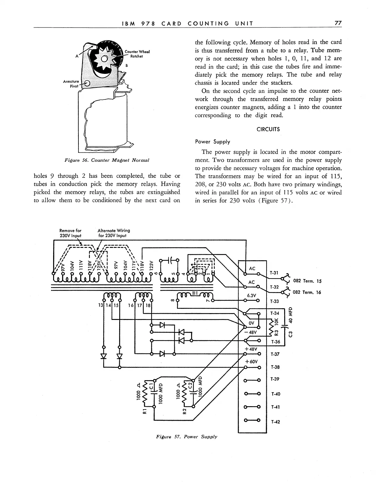
Power Supply
The
power supply
is
located in the motor compart-
ment. Two transformers are used in the power supply
to provide the necessary voltages for machine operation.
The
transformers may be wired for an input
of
115,
208, or 230 volts AC. Both have two primary windings,
wired in parallel
for an input of 115 volts
AC
or wired
in series for 230 volts (Figure
57).
082
Term.
15
082 Term. 16
T·37
T·38
T·39
0--0
T-40
0--0
T-41
~
T-42
Figure
57.
Power
Supply