78
SPECIAL
DEVICES
115~
±1:.....3
~
10
Compensating
flux lines to travel around the core and up through
the center instead of across the area with the air spaces.
The
flux
lines through the lower center part of the
core induce a voltage into the resonant and secondary
115~
±~
o
Resonant
--
~
0
6.3
Volt
Secondary
s
±5%
windings. Connected in series with one of these wind-
ings
is
a capacitor (matched in rated
size
to the in-
ductance of the coil), that causes a high current to
flow
(resonant). Only the DC resistance of the circuit
opposes the resonating current. The high current
flow
in the resonant winding causes a magnetic
field
that
saturates the lower core area with magnetic lines of
flux.
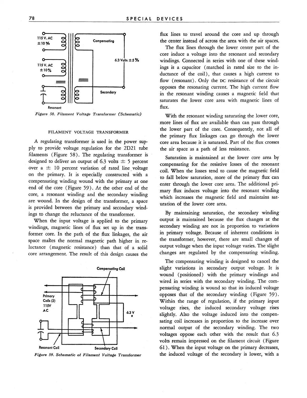
Figure 58.
Filament
Voltage
Transformer
(Schematic)
FILAMENT
VOLTAGE TRANSFORMER
A regulating transformer
is
used in the power sup-
ply to provide voltage regulation for the 2D21 tube
filaments (Figure
58).
The regulating transformer
is
designed to deliver an output of 6.3 volts + 5 percent
over a ±
10 percent variation of rated line _ voltage
on the primary.
It
is
especially constructed with a
compensating winding wound with the primary at one
end of the core (Figure
59).
At
the other end of the
core, a resonant winding and the secondary winding
are wound.
In
the design of the transformer, a space
is
provided between the primary and secondary wind-
ings to change the reluctance of the transformer.
When
the input voltage
is
applied to the primary
windings, magnetic lines of
flux
set up in the trans-
former core.
In
the path of the
flux
linkages, the air
space makes the normal magnetic path higher in
re-
luctance (magnetic resistance )
~han
that of a solid
core arrangement. The result of this design causes the
Primary
Calls
(2)
115V
AC
Resonant
Coil
Compensating
Coil
Secondary
Coil
6.3 V
II
Figure
59.
Schematic
of
Filament
Voltage
Transformer
With
the resonant winding saturating the lower core,
more lines of
flux
are available than can pass through
the lower part of the core. Consequently, not all of
the primary
flux
linkages can go through the lower
core area because it
is
saturated. Part of the
flux
crosses
the air space
as
a path of
less
resistance.
Saturation
is
maintained at the lower core area
by
compensating for the resistive
losses
of the resonant
coil.
When
the
losses
tend to cause the magnetic field
to fall below saturation, more of the primary
flux
can
enter through the lower core area. The additional
pri-
mary flux induces voltage into the resonant winding
which increases the magnetic field and maintains
sat-
uration of the lower core area.
By
maintaining saturation, the secondary winding
output
is maintained because the
flux
changes at the
secondary winding are not in proportion to variations
in primary voltage. Because of inherent conditions in
the transformer, however, there are small changes of
output voltage when the input voltage varies. The slight
changes are regulated
by
the compensating winding.
The compensating winding
is
designed to cancel
the
slight variations in secondary output voltage.
It
is
wound (positioned) with the primary windings and
wired in series with the secondary winding. The
com-
pensating winding
is
wound
so
that its induced voltage
opposes that of the secondary winding (Figure
59).
Within the range of regulation,
if
the primary input
voltage
rises,
the induced secondary voltage rises
slightly. Also the voltage induced into the
compen-
sating coil increases in proportion to the increase over
normal output of the secondary winding. The two
voltages oppose each other with the result that 6.3
volts remain impressed on the filament circuit (Figure
61).
When
the input voltage on the primary decreases,
the induced voltage of the secondary
is
lower, with a